Automotive sensor defects detected by vision
Raghava Kashyapa
Having deployed machine vision systems to automate the inspection of key components of the manifold pressure sensors it produces in Germany, Robert Bosch was eager to install a similar system at its manufacturing facility at Bosch India Ltd (Bangalore, India; www.boschindia.com). To achieve these goals, Bosch India approached Qualitas Technologies (Bangalore, India; www.qualitastech.com) to develop an industrial vision-based system to eliminate manual checking of the sensors while ensuring they would be inspected as accurately.
Different variants of manifold pressure sensors are manufactured at the Bangalore plant. They are deployed in a number of models of automobiles to measure the absolute pressure in the intake manifold that supplies a fuel/air mixture to the cylinders. Inside each sensor are two chambers separated by a flexible diaphragm printed with thick-film strain gauges. One chamber is used as a reference, while the other is connected to the intake manifold on the engine.
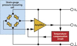
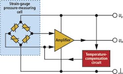
When pressure is applied to the diaphragm, the strain gauges convert mechanical strain to an electrical signal. A full-wave bridge circuit then provides a signal proportional to the applied pressure which is amplified by a hybrid circuit. A separate circuit adjusts the performance of the sensor to compensate for any changes in temperature. Three connectors from the manifold pressure sensor are used to connect the unit to an electronic control unit in the vehicle which, in turn, controls the fuel/air mixture (Figure 1).
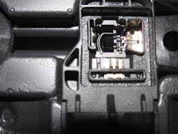
Prior to the deployment of an automated inspection system, operators would select a random number of manifold pressure sensors at the end of each production run and manually perform a visual inspection on two key features of the units - a process that took as long as 7mins per part. First, operators checked the position of two capacitors located across the three output pins of the device and then examined the position and quality of two welds that join two leads from a Negative Temperature Coefficient (NTC) thermistor to the electronic unit inside the body of the pressure sensor (Figure 2).
Automated operation
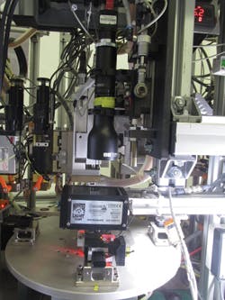
To automate the process, Qualitas Technologies developed a dual camera turntable-based system that inspects the capacitors and the welds as they are moved through two of four stations. The sensors are manually loaded into the system at the first station after which the capacitors are inspected for positional accuracy. Then, the unit is rotated to the second station where the NTC thermistor leads are inserted. At the third station the leads are welded onto a sensor base plate. Following the welding operation, the unit is transferred to the fourth station where the welds are inspected for both position and shape. After inspection, the part returns to the first station and the unit is either accepted or rejected depending on the results of the imaging operations.
The system is controlled through a graphical software interface displayed on a touch screen. The interface enables operators to select a particular variant of manifold pressure sensor from a menu, after which PC based machine control and vision inspection software convey and inspect the sensor as it travels though the four stations on the machine. The control software passes instructions to a PLC to control the movement of the table and actuators on the machine, while the machine vision software captures the images from the cameras and performs the appropriate vision inspection routines.
Because both the capacitors and the welds are inset into the plastic housing of the unit, the choice of lighting was of paramount importance to avoid the possibility of creating shadows that might otherwise affect the quality of acquired images. For this reason, both the capacitors and welds are illuminated using blue diffuse on-axis lights from Spectrum Illumination (Montague, MI, USA; www.spectrumillumination.com) mounted below two Point Grey (Richmond, BC, Canada; www.ptgrey.com) 5Mpixel cameras at each of the imaging stations. With this coaxial lighting, the specular surfaces perpendicular to the camera appear bright, while the other surfaces of the manifold pressure sensors absorb light and appear dark.
Since the position of the capacitors and the welds needed to be measured to an accuracy of within 10 microns, it was important to capture high contrast images with low geometrical distortion and ensure that any change of magnification was eliminated when the capacitors and welds were not precisely positioned. Furthermore, it was vital to ensure that there was a sufficient working distance between the base of the lens fitted to the camera and the parts under inspection. To achieve this, an ED-62-932 telecentric lens from Edmund Optics (Barrington, NJ, USA; www.edmundoptics.com) was fitted to one Point Grey camera to capture images of the capacitors (Figure 3) while a TEC-55 lens from Computar (Commack, NY, USA; www.computar.com) was mounted to the other camera to image the welds.
A notable difference between the variants of the manifold pressure sensors is the height at which the capacitors across the terminals protrude from the interior plastic casing of the sensor assembly. To accommodate those differences, the camera at the first station is fitted to a pneumatic actuator, which enables the focal distance from the camera to the part to be adjusted prior to inspection under PC/PLC control.
Software inspection
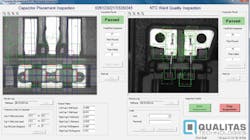
After the 5Mpixel Point Grey camera at the first imaging station has captured an image of the two capacitors across the three terminals, the image data is transferred over a Firewire interface to the PC. There it is analyzed by Teledyne DALSA's (Waterloo, Ontario, Canada; www.teledynedalsa.com) Sherlock machine vision software to determine whether each capacitor has been affixed to the terminal at an acceptable location and then measure the number of degrees by which each capacitor might be tilted off axis (Figure 4 left).
To do so, the software finds regions of interest (ROIs) in the image (shown in green) that indicate where the top, bottom and two sides of the three terminals are to be found. In addition, it also identifies the potential location of the left, right and top and bottom edges of the capacitors. An edge detection algorithm is then used within those ROIs to determine where the edges of the terminals and the capacitors are in the image (shown in red). Having found both, the location of the capacitors with respect to their position on the terminals can be derived. The system can then decide whether the position of the capacitors falls within acceptable tolerance levels.
To determine the degree to which each capacitor might be tilted, a line projection tool (shown in blue) is used to create lines of best fit between the top, bottom and side edges of the terminals as well as the top, bottom and side edges of the capacitors. From these lines of best fit, the orientation of both the terminal and the capacitor can be derived. By analyzing the differences between the two, the angle at which the capacitor is tilted with respect to the terminal can be determined.
Having inspected the capacitors, the system then rotates the table, bringing the manifold pressure sensor to the second station where the NTC leads are inserted into the terminals. Then it is moved to the third station for welding. Once the welding operation is completed, the sensor is rotated to the fourth station where the second 5Mpixel Point Grey camera captures an image of two wires emanating from the internal circuitry of the sensor and the terminals to which they are wired. This image is transferred to the PC over the Firewire interface where it is also analyzed using the Sherlock machine vision software (Figure 4 right).
Two important image processing operations are performed by the machine vision software at this stage - the first to ensure that the wires are at the correct location on the sensor and the second to check the integrity of the welds joining the wires to the terminal.
To check the location of the wires, the software finds three ROIs in the images of each of the two terminals - specifically, the sharp corner edge of the terminals and their top and corner sides (shown in green). An edge correlation algorithm then determines the location of the sharp 90 degree edges (shown in purple) of each terminal, while an edge detection algorithm detects their top and corner edges (shown in red). Based on the three measurements, the position of the terminals in the housing can then be calculated.
Having determined the position of the 90 degree corner edge of the terminal, further ROIs are derived from it which indicates the likely position of both the wires and the location of the welds. To determine the location of each of the wires at three specific places in the sensor housing, pattern matching is performed over three of the ROIs to ascertain the location of the wires. Having done so, the software then compares the location of the wires with that of the terminal to determine whether the wires are positioned accurately in the unit.
Since known good welds are always consistent and uniform in shape, it was possible to use a pattern matching algorithm to determine the integrity of the welds. To do so, the system was trained using a golden template derived from a number of known good images of welds. In operation, the images of the welds captured by the camera are compared to the golden template after which the system software determines the correlation between the acquired images of the welds and the template. The location of the weld pattern is also compared to the location of the terminal to ensure that the wire has been welded to the terminal at the desired location.
With both inspection operations completed, the part is returned to the first station where the operator unloads the inspected parts, discards those that have failed to meet the pre-set requirements and passes acceptable parts on for further processing.
Proof of effectiveness
To prove the effectiveness of the automated inspection system prior to installation in the Bosch production line, Qualitas Technologies' engineers saved over 2000 images of manifold pressure sensors that had passed and failed the inspection procedure over a period of four weeks. The results were then compared to the results achieved by manual operators. The analysis revealed that the vision inspection system could inspect the welds 95% as accurately as a human operator and the capacitors 99% as effectively.
The Qualitas Technologies' manifold pressure sensor inspection system has been installed at the Bosch manufacturing facility for over one year. Since then, it has been inspecting approximately 5,000 manifold pressure sensors per day. What is more, the complete inspection and welding process takes just 10s per sensor, a noticeable reduction in time compared with the 7mins taken to inspect the parts manually. Bosch Limited is so satisfied with the improvements in efficiency and speed the system provides, that it has commissioned Qualitas Technologies to build two more systems.
Raghava Kashyapa, Managing Director, Qualitas Technologies, Bangalore, India
Companies mentioned
Computar
Commack, NY, USA
http://computar.com
Edmund Optics
Barrington, NJ, USA
www.edmundoptics.com
Point Grey
Richmond, BC, Canada
www.ptgrey.com
Qualitas Technologies
Bangalore, India
www.qualitastech.com
Spectrum Illumination
Montague, MI, USA
www.spectrumillumination.com
Teledyne DALSA
Waterloo, Ontario, Canada
www.teledynedalsa.com
