Vision-guided system speeds F/A-22 assembly
Smart cameras, LED arrays, and actuators create “vision pins” to align fuselage sections.
By C. G. Masi, Contributing Editor
Lockheed Martin, the prime contractor on the US Air Force next-generation fighter aircraft, the F/A-22 Raptor, has the fuselage of the aircraft built in three sections (forward, mid, and aft) in three separate locations, then ships sections for final assembly to its Marietta, GA, plant, where it builds the forward fuselage. The mid-section is built in the company’s Wichita, KS, facility, which the company acquired from General Dynamics (a second member of the original F/A-22 development team). Boeing (the third member of the original team) builds the aft section and wings in its Seattle, WA, plant. This situation creates a challenge for the team at the Marietta facility, which needs to mate the mid and aft sections precisely so that the wings will slip over 18 fastening lugs, half of which are built into the mid section and half into the aft section.
In addition, the wings are field-replaceable units, which means the lugs have to be placed accurately enough that any wings in the field inventory will fit on without modification. And the aircraft’s performance specifications include speeds up to Mach 2 and turning loads that are classified but known to be beyond the capabilities of current aircraft. So the manufacturing tolerances must be very tight to provide the necessary reliability. These requirements also mean that when the team at the Marietta plant puts the mid and aft sections together it has to locate all the wing lugs to within 0.004 in. (100 μm)-an extreme precision when the lugs are spaced around a wing-root mating surface measuring approximately 20 feet (6.2 m) × 2 feet (0.61 m; see Fig. 1).
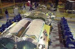
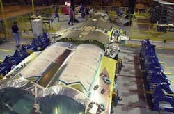
FIGURE 1. Fuselage for the US Air Force F/A-22 Raptor arrives at Lockheed Martin’s assembly facility in three pieces that must be fitted together with sufficient precision that any set of field-replaceable wings will simply fit over their attaching wing lugs. The gold portion is the fuselage mid-section (top) and the whiter portion is the aft section (bottom). The blue structures on either side are fixture points for mounting the wings.
null
VISION ALIGNMENT
To solve this problem, Lockheed called on systems- integrator Delta Sigma. “We’ve been involved with this airplane on the research side for about 18 years-ever since the RFQ came through from the Air Force,” says company president Roger Richardson. “They had 14 or 15 ships at the time we started working on this production problem, and they needed to be ready [for full production] by ship 20.”
When Delta Sigma first started working on the problem, it took a crew of four engineers and two technicians four to five hours to align the fuselage sections before fastening them together. “The engineers would be out there with feeler gauges and micrometers making measurements all around the airplane,” Richardson recalls, “and they would be telling the technicians, ‘turn this screw, turn that screw,’ but, of course, the definition of a rigid body is that if you move one part then all the other parts move.” Every time they would move one of the fuselage sections to improve the alignment of one wing lug, all the other wing lugs would move, too. That made a very complicated three-dimensional geometry problem for them to solve.
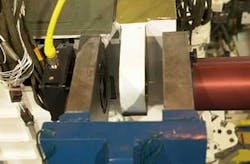
The heart of the automated alignment system that Delta Sigma developed for Lockheed Martin consists of a number of “vision pins” consisting of a DVT 540M smart camera and an IDRA LED array light source mounted in the arms of a clevis-shaped fixture. During alignment, the clevis arms straddle one of the wing lugs attached to the fuselage (see Fig. 2). A pinhole target fits in the exact center of the wing lug, projecting a visible target on the camera’s image plane. The engineers refer to this system as a vision pin because it is analogous to a physical pin that might be used in a manual alignment process.
FIGURE 2. To achieve the critical alignment specification quickly, a “vision pin” incorporates a DVT M540 smart camera mounted on the red anodized-aluminum housing and a DVT IRDA LED array light source. During alignment, a plug with a pinhole within a few ten-thousandths of an inch fits into the wing lug that the vision pin is to locate. The camera can determine the pinhole’s location within 0.001 in. laterally by determining its location within its field of view, and its position along the camera’s optical axis by measuring the pinhole’s apparent diameter.
The target’s position on the camera’s image plane signals the wing lug’s transverse (left-right and up-down axes of the aircraft) position with respect to the camera. Its diameter on the image plane signals its forward-aft location relative to the camera. In this way, a vision pin can locate a wing lug to within 0.001 in. (25 μm) in three dimensions.
Since the cameras have on-board intelligence, they are capable of making all of the calculations needed and can send a signal over an Ethernet link reporting the offset (in three dimensions) needed to move the wing lug to the correct location.
PULLING TOGETHER
The engineers use alignment fixtures to align the light pins relative to each other. The fixtures provide clevis structures with relative locations matching the lugs mounted on the wing roots. Engineers set eight light pins up in each fixture. Four of these light pins locate wing lugs on the mid fuselage section and four locate lugs on the aft section. A similar fixture provides locations for the corresponding light pins representing lugs on the other wing.
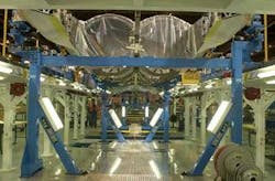
Electromechanical actuators located underneath the fuselage sections support and move the lugs (see Fig. 3). These actuators move both fuselage halves until the wing lugs line up with their corresponding light pins to within the required 0.004-in. tolerance. On each fuselage section there are four vertical actuators to raise or lower the corners-two that move the section left and right and one to move it forward and backward.
The four vertical actuators provide controlled motions around roll and pitch rotational axes, and translational motion along the vertical axis:
- moving all four actuators in unison gives vertical displacement
- moving the two actuators on the right opposite those on the left produces roll movement
- moving the forward actuators opposite the aft actuators produces pitch movement.
The two transverse (left-right) actuators produce transverse and yaw motions:
- moving both actuators together moves the section transversally
- moving both actuators opposite each other produces a yaw motion.
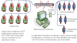
The single longitudinal (forward-aft) actuator provides controlled displacement along the aircraft’s long axis. The smart cameras in the eight light pins (four for each wing root) are capable of analyzing the images they see of their targets and putting out a 3-D vector representing their offsets from the ideal locations (see Fig. 4). Those locations are sent over the Ethernet to a central host Dell PC, which convolves the eight vector offsets from the eight light pins and works out a set of displacements for the linear actuators that will correct all of the offsets to within tolerance.
FIGURE 4. The F/A-22 fuselage assembly system has three main components-vision pins, PC, actuators-interlinked by Ethernet. For each aircraft section, four vision pins measure the position of each wing root and compute offsets needed to bring it into alignment. A PC uses those offsets to compute displacements needed by seven smart linear actuators to bring the fuselage sections into alignment so that the wings will slip on. (There are actually 14 actuators, seven for each section.)
The host PC then sends those results over the Ethernet to Allen-Bradley Micrologix 1200 PLCs controlling each of the linear actuators. Each linear actuator comprises the PLC, an encoder, and a motor. The PLC adds the offset to the current encoder value to get a new target value, then drives the motor until the encoder output reaches the target value.
This automated vision-enabled alignment system is much faster and more accurate than the old manual system. The vision pins provide more accurate and reliable offsets than manual measurements, and the host computer can solve the geometry problem in a fraction of the time human engineers took.
features, advantages, benefits
Greg Young, tool engineer in the body mate area at Lockheed Martin’s Marietta, GA, plant, says, “The main feature of the fuselage-alignment system is that it is completely controlled through the computer. It automatically moves to within a few thousandths of an inch of perfect alignment and allows us to ‘manually’ move it in even closer than that.”
He adds, “We can manually put corrections in through the computer, and the machine makes the adjustments. This computerized system provides savings in time and improvements in accuracy. The system is easy to learn as well. We are very happy with it.”
Company Info
Allen-Bradley Milwaukee, WI, USA www.ab.com
Boeing Seattle, WA, USA www.boeing.com
Dell Computers Austin, TX, USA www.dell.com
Delta Sigma Acworth, GA, USA deltasigmacompany.com
DVT Duluth, GA, USA www.dvtsensors.com
General Dynamics Falls Church, VA, USALockheed Martin Marietta, GA, USA www.lockheedmartin.com
