Robots and vision assemble diagnostic devices
Pregnancy test kits are inspected and assembled in a series of work cells.
By Andrew Wilson, Editor
Automated systems for medical-device manufacturing are now combining robots and vision systems for part feeding and automated assembly operations. These systems include interchangeable part fixtures and preprogrammed assembly manufacturing techniques to provide configurable automated assembly systems.
"Automated assembly systems for diagnostic-device manufacturing must accommodate frequent product changes and new product introductions," says David Stroup, chairman and chief technology officer of Prodosyst Automation, a systems integrator and designer of turnkey automation systems. "Because of this, diagnostic-device manufacturers demand automated systems that can perform quick part changeovers and adapt to new product specifications." The company has developed a number of systems tailored to meet its customer's production needs in industries including biodiagnostics, medical devices, genomics, pharmaceuticals, and life sciences.
NO BOWL FEEDERS
"Using robotics and vision systems, individual product parts can be fed into the assembly process without relying on dedicated bowl feeders and part-specific escapements," says Stroup. "When such systems are coupled with interchangeable part fixtures and preprogrammed assembly recipes, part changeover can be achieved with minimum delays and risk. Such systems allow easy access to all part feeders, robots, and electrical panels, minimizing maintenance and downtime."
"Historically," says Stroup, "disposable pharmaceutical products such as pregnancy test kits were manufactured using product-specific discrete pick-and-place machines. However, with the demand for shorter production runs and the introduction of a variety of 'boutique' diagnostic testing products, manufacturers started to demand sophisticated systems capable of manufacturing a number of products." By automating the assembly of tens of thousands of such products per year, these systems eliminate the errors found in manual assembly, increase product quality, and eliminate manual-labor costs.
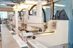
To automate the production of its diagnostic test kits, Applied Biotech Inc. called on Prodosyst to develop a system based on off-the-shelf robots and vision technology (see Fig. 1). "Because the company assembles approximately 20 different products," says Stroup, "it was necessary to build a system that could be adapted to automate the assembly of each one." Early on, Prodosyst engineers realized that they needed a system based on a series of work cells that could be married together to automate the assembly process.
Prodosyst selected four Adept Cobra s600 SCARA robots with Adept's ObjectFinder locator tool. The completed TrueFlex system uses robots and vision systems, together with interchangeable part fixtures, to allow manufacturers to build discrete products. Each robot includes an embedded multichannel amplifier, options for vision-guided motion, conveyor tracking, and auxiliary axes for automation. Using the Adept SmartServo architecture, multiple robots can be controlled and coordinated from a single Adept controller. AdeptVision AVI—Adept's vision package—includes Adept ObjectFinder, a vision tool that recognizes multiple objects and patterns and discerns orientation and scale.
MARRIED TOGETHER
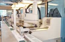
In the assembly of a pregnancy test kit, five individual components must be married together seamlessly. These include the base of the product, a wick, a diagnostic test strip, the top of the product, and a cap. To perform the assembly, the base of the product must be placed in a palette (an opaque plastic "nest") after which the other elements of the product can be placed in sequence. This nest moves along a process indexer that allows each component to be placed serially into the nest as it arrives at each work cell (see Fig. 2).
In the first work cell, component base parts are fed perpendicularly along a Dorner Manufacturing 2200 series conveyor to the assembly station. There, a GPMF602 camera from Panasonic Vision Systems determines whether the part is upside down or right side up, and at what angular orientation. Images from the camera, located approximately 2 ft from the conveyor belt, are digitized by an Adept frame grabber that is housed in the PC-based Adept 600 robot controller.
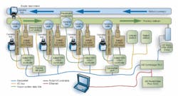
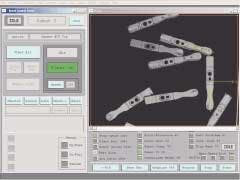
Here, geometric pattern matching software, originally developed by Hexavision and integrated as Adept's AdeptVision software, determines the orientation of the base part. After the system determines that the base part is upside down, it can be placed in the palette (see Fig. 3). Before the base part of the test kit is positioned, however, the system also checks the palette to ensure it is empty and ready to receive parts. To do so requires an additional Panasonic camera. After this check is complete, the base is positioned in the palette.
After the base is positioned, a membrane must be placed at the center of the midstream test kit. Rather than use a flexible automation robot for this task, Prodosyst developed its own proprietary membrane cut-and-place station. At a rotary servo-driven, dual-head, pick-and-place cell, the membrane is placed into the base of the product before it is indexed to the next robot/vision work cell.
In a similar fashion to the first work cell, individual wicks are conveyed in random order to the second work cell using an Adept FlexFeeder 250 conveyor. "Because the wicks are dimensionally smaller than the base of the product, a smaller conveyor belt can be used," explains Stroup. To determine the position and orientation of these wicks, a similar robot-vision setup is used. At this work cell, it is necessary to determine the center of each wick, as well as its orientation.
BACKLIGHTING
Using a backlight under the conveyor belt, the outlines of the wicks can be imaged easily and their centroids determined with the AdeptVision software. "Because each wick has a flat side and a corregated side," says Stroup, "it is also necessary to image the side of the part with a separate camera." Once the orientation of the part is determined, the wick is placed in the base of the midstream test kit and the product indexed to a placement-inspection station.
"Rather than place the top of the test kit on the partially assembled device," says Stroup, "it is necessary to check whether the base, membrane, and wick are correctly placed before final assembly." To accomplish this, another GPMF602 camera from Panasonic images the partially assembled kit to check the x, y position of the membrane and wick and their angular position. If these parts are in position and correctly placed, the part is moved to the next stage of assembly. If they are incorrectly assembled, no further automated assembly occurs, the parts are tracked by a Contrologix programmable logic controller from Allen-Bradley and finally rejected for recycling at the end of the assembly line.
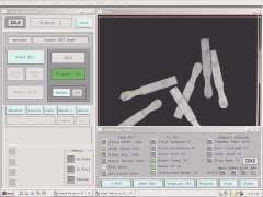
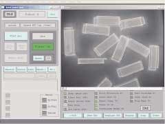
Correctly assembled components are moved to the third work cell. Here, the top of each product is fed to the work cell on another Dorner 2200 Series conveyor. Using similar methods to the first work cell, component top parts are fed perpendicularly from this conveyor to two Panasonic GPMF602 cameras that inspect whether the part is upside down or right side up, and at what angular orientation (see Fig. 4). AdeptVision software then guides the top of the test kit to the nest where it is placed by lining up a series of pins and sockets.
PRESSED FOR TIME
After a press station fixes the top and bottom of the component parts together, individual caps must be placed on the end of each kit. Here again, two cameras inspect the caps as they move along an Adept FlexFeeder 250 conveyor into the final work cell (see Fig. 5). "One of the challenges with placing the caps on the wick end of these test kits," says Stroup, "is that in some cases these parts are transparent."
Thus, not only must the system determine the orientation of the caps as they move along the conveyor, it must image the side of the caps to locate a small clear clip located on a single side of the cap. In this way, the integrity and correct orientation of the cap are determined. To position the cap correctly on the finished assembled kits, an Adept SCARA robot lifts the final part from the nest and places the cap correctly at the wick end. The final product is placed back on the indexer and moved to an unload station for further automated packaging.
For operator ease of use, Prodosyst engineers developed a touch-screen interface using Rockwell RSView and Adept PC for Windows. This interface allows operators to start and stop the machine, "home" the machine, and change the type of product being inspected. An operator selects the product to be assembled from the touch screen, which determines the inspection tasks and the number of robots, then changes the components that are fed along each conveyor. "In this way," says Stroup, "the system can be tailored to meet the needs of many different types of automated manufacturing situations."
"With a cost of between $700,000 and $900,000, depending on the type of product to be assembled," says Stroup, "this system can manufacture between 40 and 60 parts per minute. With a yield of approximately 99%, the system has been used to automate the assembly of products that previously required between 20 and 30 people."
Company Info
Adept Technology, Livermore, CA, USA www.adept.com
Allen-Bradley, Milwaukee, WI, USA www.ab.com
Applied Biotech Inc., San Diego, CA, USA www.abiapogent.com
Dorner Manufacturing, Hartland, WI, USA www.dorner.com
Panasonic Vision Systems, Secaucus, NJ, USA www.panasonic.com/visionsystems
Prodosyst Automation, San Diego, CA, USA www.prodosyst.com
Rockwell Automation, Milwaukee, WI, USA www.software.rockwell.com
