Automated inspection station rejects defects
Smart camera, strobed LED array, and PLC inspect injection-molded parts.
By C. G. Masi, Contributing Editor
Shinsei USA manufactured approximately 3 billion injection-molded parts last year, and inspection throughput is a critical element in maintaining production speed and quality. From the injection-molder equipment, parts flow through feeder bowls to an automated stocking system. Until recently, the company conducted quality assurance by pulling parts out of the finished stock for manual inspection. The introduction of an automated machine-vision inspection system developed by systems-integrator Delta Sigma has provided a much quicker, complete, and more cost-effective alternative.
"The automated inspection system fits in line between the feeder and stocker," according to Tom Ashley, assistant operations manager at Shinsei's Precision Injection Molding Facility in Peachtree, GA. "It inspects every part at production speed—a feat that was impossible for manual inspectors. It's also much more accurate, catching defects that would have been passed by the old manual system."
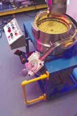
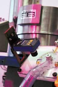
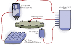
Parts from an injection molder drop into the feed bowl atop the inspection system. The feeder system automatically lines parts exiting the bowl along a ramp and orients them for presentation to the camera (see Fig. 1). The parts drop from the injection molder into a feeder bowl, which lines them up and orients them to drop into an indexing wheel at the inspection station input. The wheel has slots around its perimeter in which the parts just fit. These slots encourage parts to slip into the correct spot for the inspection system to view and to drop out easily when the slot reaches the good-part output station (see Fig. 2 on p. 37).
The wheel makes a brief stop at each station. At the first station, a DVT 540M SmartImage Sensor views the part silhouetted against the bright, diffused-light LED array panel. The DVT IDRA red LED array is approximately 3 × 3 in. across and evenly lit, providing a diffuse source backlight for inspecting the part. A puff of air at the next station blows rejected parts into a reject tube. Good parts drop out at the next station into a bin beneath the machine. There is room for additional stations where parts could be tapped off into other output streams.
BENEFITS OF STROBING
The inspection system's primary target when inspecting opaque parts, such as fuel-injector caps, is the "flash," which is a mold mark surrounding the component's outer edge or intruding into the central orifice. Strobing the array provides a rapid image capture and a relatively long time between strobes to process the image while indexing the mechanical system.
Strobing the LED array shortens the current duty cycle, reducing the average power dissipation and lowering the junction temperature. Within limits, the LED array can be overdriven by a factor approximately equal to the inverse of the duty cycle. In other words, keeping the duty cycle to 25% allows overdriving the LED array by a factor of four. That (theoretically) increases the output brightness by a factor of four, making it possible to drive four times as much light through the translucent plastic of the part. It also increases the contrast introduced by an opaque inclusion.
Strobing also speeds up the inspection process. A bright strobed LED illumination panel can stop motion of a part across the camera's field of view, or allow fast image capture to minimize the inspection time.
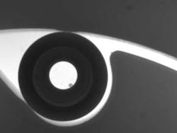
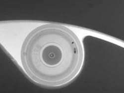
The system rejects parts such as the fuel-injector cap because of a bit of "flash" visible in a center hole. It appears as a small circular shadow attached to the inside edge of the hole (see Fig. 3).
Battery caps are bowler-hat-shaped parts made from translucent plastic that present a different inspection challenge. The inspection system has to find opaque inclusions within the translucent material of the cap, which attenuates light rather than completely blocking it. Opaque inclusions appear as small black granules (see Fig. 4). The system can discern opaque inclusions that are too small for the human eye to see. These granules do not affect the part's mechanical or chemical properties, but do affect its appearance.
INSPECTION BALLET
An Allen-Bradley Micrologix 1200 programmable logic controller (PLC) with Ethernet interface has overall system control, beginning when it signals the indexing-wheel drive to cycle. This brings a new part under the camera for inspection, the part previously inspected moves into the rejection station, and the part that was in the rejection station (assuming it was not rejected) moves into the good-part station, where it drops out into the good-part bin.
The PLC stops the indexing wheel and sends a trigger signal to the camera to collect an image. The camera triggers the electronic shutter on the LED array to open and strobes the part, takes an image, and begins analysis. LEDs operate at low voltages—24 V in the case of the IDRA array—and their light output tracks the supply current. Thus, all the LED power supply needs to do is generate a square pulse at 24 V with enough drive current to power the array.
The system as programmed relies mainly on pattern recognition to isolate anomalies in the image caused by inclusions or flash. These image-analysis routines are native functions of the camera operating system, FrameWork 2.7. Blob-area analysis provides the main indicator of severity. For example, inclusions that are below a preset threshold (which relates to the minimum observable by eye) can be ignored, while bigger ones are cause for rejection. On the other hand, the large but faint shadow seen on the left side of Figure 4 is large enough to reject, but is too faint to be easily visible.
While the camera is processing an image, the indexing wheel steps to the next position. The imaged part, therefore, reaches the reject station as the camera determines whether to pass it or not. If the camera rejects the part, it sends a signal to the PLC to send a puff of compressed air from a nozzle beneath the indexing wheel that blows the part up out of its slot and into the reject tube, then steps the indexing wheel to the next station. If the camera accepts the part, it signals the PLC, which simply steps the wheel.
At this point, the wheel has stepped three times: once to bring the part under the inspection camera's lens, a second time to move it to the reject station, and a third time to bring it to the good-part station. Each time the wheel steps, it brings a new part in so it can step through the process in turn.
"The advantage of using LED lighting," says Roger Richardson, president of Delta Sigma, "is that we can inspect parts with only one camera. Right now we're running 248 parts per minute, but we have run it at more than 300 parts per minute and it works just fine."
Another LED advantage is reliability. Unlike incandescent and strobe lamps, LEDs are solid-state devices with no normal-wear mechanism. That is, as long as the devices do not overheat, they will last indefinitely. Richardson says that one of his customers has been using a similar machine for two years without a hitch. The customer has been strobing it faster than once per second on a 24/7 basis for two years—or more than 63 million flashes without a failure.
Shinsei's Ashley says, "We're still barely scratching the surface of what this technology can do. In the future, we expect it to inspect for hub voids and gate vestiges, which we simply could not do with the old manual system."
Company Info
Allen Bradley, Milwaukee, WI, USA www.ab.com
Delta Sigma, Acworth, GA, USA www.deltasigmacompany.com
DVT Systems, Duluth, GA, USA www.dvtsensors.com
Shinsei USA, Peachtree City, GA, USA www.shinseiusa.com
