INDUSTRIAL AUTOMATION PRODUCTS - Programmable Logic Keeps Machine-Vision Systems Moving
Jason Eiynck, Jonnathan King, and Steve Maves
Latency and determinism are two of the most important factors that need to be considered when developing a machine-vision system. Latency—the time it takes for a machine-vision system to complete a specific task—is dependent on the algorithms used to perform a particular task and other functions, such as operating system overhead.
When these tasks are repeated, the time to complete individual operations will vary, producing a measure of jitter in the system. In most machine-vision systems, a maximum guaranteed response time is demanded, for example, before a part passes a reject mechanism, resulting in the need for a deterministic system that ensures that specific tasks are processed in a given amount of time.
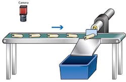
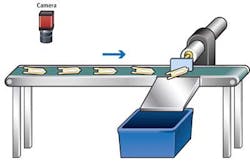
In machine-vision systems, image-processing tasks are inherently nondeterministic, but the results of any inspection are not required until the part reaches the reject mechanism (see Fig. 1). If this machine indexes one part per second, then the vision system must have a throughput of less than one part per second on average. However, if an individual result takes longer than one second, there is no reason for the machine to generate a stop signal since the inspection result is not required for another four seconds.
As long as the average throughput of the vision system remains less than one part per second, the system will perform as required. This can be achieved by using a vision system with built-in image buffering, which allows each successive inspection to be triggered before the previous inspection has ended. Adding a small amount of I/O and additional logic to the higher-level control system also ensures sufficient system performance.
Programmable logic
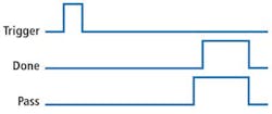
Many automated systems use programmable logic controllers (PLCs) for higher-level machine control. When initiating an inspection, the PLC asserts a trigger signal once per machine cycle. At the end of the cycle, the vision system indicates a Pass or Fail status and an additional signal, in this case, called Done. These three signals have been the minimum I/O configuration for a best-practice vision "handshake" for some time. This configuration allows the PLC to create a fault if the vision system does not generate a result (Done) signal by the time it is ready to trigger the camera again (see Fig. 2).
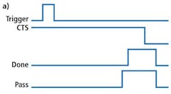
Here, we are recommending another signal: the "Clear to Send" signal. This signal is output from the PLC to the vision system, indicating that the PLC is ready to receive data. If the PLC is not ready to receive data, it can de-assert this signal and the vision system will wait to send results—allowing the PLC to index the machine and move on if the vision system does not have the results, enabling it to catch up at a later time.
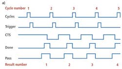
When the PLC is ready for data, the Clear to Send signal is asserted (see Fig. 3a). When the vision system has results, the Inspection Done signal is output from the vision system to the PLC. The Inspection Done signal is not asserted until the vision system has set all the Pass/Fail outputs for the rest of the inspection. When the PLC senses that the Done signal is on, it reads the other Pass/Fail signals and de-asserts the Clear to Send signal, indicating to the vision system that the inspection cycle is complete and the PLC has data. The vision system will then de-assert the Done signal and any remaining pass signals. The combination of the Done output from the vision system and the Clear to Send output from the PLC forms a fully synchronized, bidirectional handshake between the two systems that decouples machine-vision triggers and machine-vision results.
Of course, the Pass signal is never asserted unless the part passes inspection. Furthermore, the Pass signal state is always set before the end of the machine-vision cycle when the Done bit is set. Although Fig. 3a does not show it, a vision system with image buffering is capable of receiving another trigger before the inspection cycle ends.
Programming
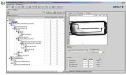
By placing inspection results in an indexed shift register in the PLC, the vision system results can operate "out of cycle" with the rest of the machine before parts are rejected or a fault condition occurs. To complete the handshake with the PLC, the vision system must poll the inputs to determine whether the Clear to Send signal is asserted or not. Then, after the results are sent, the vision system must ensure the Clear to Send signal is de-asserted before the end of the inspection. This can be accomplished utilizing a vision system with nested loops, as shown in Fig. 3b.
Using the code
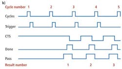
In situations where the total vision inspection time is less than the machine cycle time, the additional complexity of the PLC program is not required since the Clear to Send signal falls within the machine cycle time and the machine is deterministic (see Fig. 4a). Additionally, where the inspection time takes longer than one machine cycle time to complete, the vision system does not have a new result for the PLC after the first trigger (see Fig. 4b). However, by buffering the image data, all subsequent inspections are performed in a deterministic way so the PLC program is again not required.
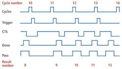
In cases where the vision system is less deterministic, the vision inspection task may be longer than the machine cycle time (see Fig. 5). For example, if some event occurs such as a user interface interaction or Windows housekeeping during Machine Cycle 10, the vision system results fall behind. During the start of Machine Cycle 11, the vision system is three parts behind. During the next two machine cycles, the vision system catches up, and by the end of Machine Cycle 13, the results are only one part behind again. Utilizing vision systems with image buffering enables this type of "catch-up" capability and the Clear to Send handshaking scheme described here.
Jason Eiynck is director of engineering at Jamarac Automation; Jonnathan King is managing member at Work Digital; and Steve Maves is manager of application engineering at PPT Vision (Bloomington, MN, USA).
