MICROSCOPY: Automated microscopy system reads microbead barcodes
By combining photolithographic digital barcodes with immuno- and molecular chemistry, Applied BioCode Inc. (Santa Fe Springs, CA, USA) has created a Barcoded Magnetic Bead (BMB) technology designed to improve the isolation and identification capacity of in vitro diagnostics.
The microbeads that the company has developed feature an inorganic core surrounded by an outer layer that consists of nucleic acids, proteins, or other probe molecules. Through a digital barcode, each BMB microbead is encoded with the information of a specific biological probe immobilized on its surface.
After multiple probes—each with a different signature—are placed in a microtiter well and hybridized with DNA cell samples, for example, fluorescence may occur. By measuring the barcode of each fluorescent bead, various types of diseases can be analyzed in a single microtiter well plate.
To prototype a medical diagnostic instrument for identification of these microbeads, Applied BioCode called upon MoviMED (Irvine, CA, USA) to develop an inverted microscope-based system capable of reading approximately 500 beads/well from a standard 96-well microtiter plate in less than an hour.
"Each bead contains a 5-bit custom barcode that is placed in a 100 × 30-µm rectangle on the bead," says Markus Tarin, president and CEO of MoviMED. "To image the large number of beads in each well, the microscope-based system was required to scan each well and then process the images to ignore broken and overlapping beads."
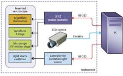
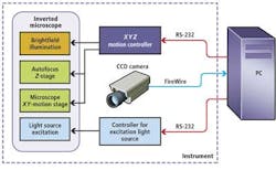
In the prototype system, an MS-2000 XYZ stage and motion controller from Applied Scientific Instrumentation (ASI; Eugene, OR, USA) was interfaced to servo motors to control the X-Y motion of the microscopic stage and focus (Z) of an off-the-shelf microscope (see Fig. 1). To capture barcode data, brightfield illumination was first used to produce a visible image of the microbead. By analyzing the maximum standard variation in gray levels within each image, the system could then be focused automatically. After this image is captured, a mercury discharge lamp, together with a matched green bandpass filter, is used to provide an excitation light source of the same field of view. In this way, both the image of the barcode and any fluorescence associated with it could be captured using an ORCA-AG 1344x1024, IEEE-1394, DCAM-compliant off-the-shelf FireWire camera from Hamamatsu (Bridgewater, NJ, USA) also interfaced to the PC.
To attain the 1-µm/pixel resolution required by the system, the X-Y stage of the microscope was moved across each of the microtiter plates to produce 35 images of each well. This image stitching needs to be accurate to within 1 pixel so the system can accurately read beads that may extend into an adjacent image. The images were then composited in the PC to produce a final high-resolution image.
After both brightfield and fluorescent images are captured, background correction is performed on the brightfield image to isolate the microbeads and their barcodes. Since multiple microbeads are placed in each microtiter well, overlapping beads are commonplace. To isolate these, a rectangular area filter ranging from 25 to 150 pixels is used. This is followed by a morphological dilation operation that adds pixels to the boundaries of objects in an image and a larger area filter to further isolate barcodes. Finally, geometric pattern matching is used to detect the shape of each microbead.
"Although geometric pattern matching may locate the proper shape of the microbead," says Tarin, "the barcode may be incomplete. In such cases, only those microbeads of the correct shape and complete barcode are identified by the system."
Because the barcode stripes fluoresce with different intensity than the outer layer of molecules on the bead body, it is necessary to eliminate this effect to properly measure the level of fluorescence of the molecules. The brightfield image is therefore masked with the fluorescence image, resulting in an image that more accurately depicts the level of chemical fluorescence (see Fig. 2).
After four months of prototyping, the final system was delivered to Applied BioCode for evaluation. Since then, the company has redesigned the system in a number of commercially available products such as the company's BioCode-HP Analyzer. "Such systems reduce the analysis time of complex in vitro diagnostic testing from months to hours," says Tarin.


