IMAGE CAPTURE - Smart cameras inspect O-rings
The O-ring is one of the most common gaskets used in mechanical engineering. Designed to be seated in a groove and compressed during assembly between two or more parts, O-rings are used in many types of products including those found in household bathroom appliances. Often produced from synthetic compounds such as ethylene propylene diene monomer (EPDM) rubber, a type of synthetic rubber, these products are relatively easy to manufacture and can be mass produced.
To supply installers of bathroom appliances with these O-ring seals, manufacturers produce the parts in various sizes ranging from 40–135 mm in diameter. After the seals have been manufactured, they must be inspected to ensure the lack of cracks, pits or flashing that would affect the integrity of the seal once applied.
“Many companies that manufacture these seals produce them in massive quantities,” says Michael Siemer, president of Siemer Technik (Vechta, Germany), “and it is impossible to examine each individual part using manual inspection techniques.”
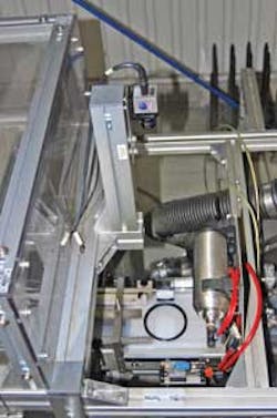
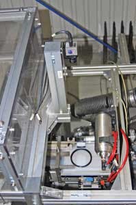
Because of this, one large European manufacturer of O-rings approached Siemer Technik with the task of developing an automated system capable of defect inspection at rates as high as 24,000 parts/hr. To manufacture O-rings at this rate, multiple machines are used to both mold and cut the parts. These parts are then fed onto 20 different conveyor belts and singulated, 20 mm apart, onto a single conveyor belt and fed to an inspection station (see Fig. 1). For this machine, Siemer chose a machine-vision inspection solution recommended by Simac Masic & TSS bv (Heerlen, the Netherlands) that includes three inspection subsystems and software from PPT Vision (Bloomington, MN, USA).
To ensure that each part is free from cracks, pits, or external flashing, it is necessary to subject the part to external stress since stretching it will allow defects to be more easily visualized. To deform the parts as they are fed through the machine, while at the same time allowing the 360° circumference of each part to be inspected, the parts must be rotated. Two linear mechanisms located at the edges of the conveyor—each moving in opposite directions—squeeze and rotate the part as it moves along the conveyor.
“This mechanism opens any cracks and flaws that may be present in the O-ring seal and allows it to be more effectively examined,” says Siemer. The inspection system establishes proper contrast for imaging the part as it is rotated through the first 180°, at rates as fast as 400 parts/min, by backlighting the part through the transparent conveyor belt using a strobed xenon light. A silhouette of the O-ring is captured by an Impact 7200 C-series intelligent camera from PPT Vision. Data from this 1024 × 768 × 8-bit CCD camera is then transferred to an Impact C Series processor/controller over a proprietary camera interface.
After the image of the part is captured, the part moves along the conveyor belt and is rotated by another 180°. Another backlighting and machine-vision substation is used to capture a second view of the part. Images from this second station are also transferred to the Impact C Series controller. In this way, two distinct images are captured that show any deformities that may occur around the complete circumference of the part.
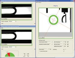
Both these cameras provide a per-pixel resolution of approximately 0.11 mm, allowing the system to detect cracks as small as 0.22 × 0.33 mm. To analyze whether each part has any defects, a number of different software tools from PPT’s Impact software suite were used (see Fig. 2). After the edges of the O-ring are located using line-finding tools, for example, blob-finding tools were used to determine whether any cracks were present along the circumference.
After the images are captured, the O-ring is released from the linear rotation mechanisms and regains its circular shape. After this process, the ring moves to the third and final inspection substation where it is again backlit and imaged by an Impact 5200, a 520 × 480 × 8-bit camera. With a resolution of 0.28 mm per pixel, the camera can detect cracks and flashes as large as 0.84 × 0.84 mm in the O-ring. Data from the camera are also fed to an Impact C Series controller. In addition to performing a final inspection of the O-ring, this stage is used to check/measure the circumference of the part and to check its circularity.
“At this stage,” says Siemer, “it is also important to check whether the O-ring is correctly oriented.” Rather than use another camera to perform this function, Simac developed a solution that employs a mirror mounted in the field of view of the Impact 5200 camera. By imaging both the O-ring and the mirror, the circularity and the orientation of the O-ring on the conveyor can be easily determined. Using origin finding and circular measurement tools, the diameter of the part is then established.
Data from all three camera systems are transferred from the Impact C series controller to a host PC where they are stored in a database format for analysis later. To date, Siemer Technik has already shipped a number of the packaging machines to its customers. Partner Simac Masic & TSS installs and maintains the vision systems at these end users’ facilities across Europe.


