Portable Laser System Patterns Panels
Andrew Bodkin
In today's high-technology field, manufacturers are continuously striving to build increasingly large multilayer panels from transparent amorphous materials. Occasionally, there is a need to add features to the patterning of the glass panels after they have left the production line. Returning them to the line for patterning with the original production equipment is too cumbersome to be practical.
To circumvent this procedure, Bodkin Design and Engineering was called upon to develop a laser-based imaging system—similar in concept to the one employed in the manufacturing process—that could be used by a single operator to modify the panel patterning in situ, after panels have been removed from the line or even after installation.
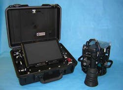
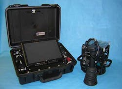
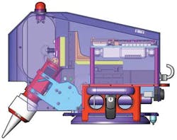
The portable Laserscribe system comprises two major subsystems: a remote handheld unit that is attached to a panel by an operator to affect a pattern change, and a portable control system connected to it through an umbilical cable (see Fig. 1).
The remote unit affixes to the panel, allowing the operator to maneuver the optical assembly via a motorized x-y-z translation stage. The optical assembly in turn is composed of an LED light source to illuminate the area of interest, a microscope camera to enable the operator to view the area of interest, and a high-power laser to modify an area of the panel. The PC-based control system software allows an operator to command the unit using a touch-screen interface.
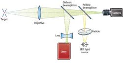
To target the exact location that requires patterning, the operator is presented with a targeting reticule projected through a pellicle beamsplitter and the main objective lens onto the glass. The reticule is backlit by a white LED illumination system from Cree.
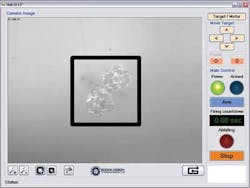
An image of the reticule on the target surface is captured by a 1280 × 1024-pixel USB camera from PixeLINK that was removed from its housing and integrated into the main optical assembly in the Laserscribe head. When the operator has located the target area, the software controls are used to plot a path around it that the laser will subsequently follow.
Once the system is activated, the translation stages come alive and light from a neodymium-doped yttrium aluminum garnet (Nd:YAG) laser from Arctic Photonics is directed through a dichroic beamsplitter, out the main objective lens, and along the plotted course. Co-boring the optical and laser pathways ensures that the laser can be accurately projected onto the target much in the way a DSLR camera shares its objective lens with both the eyepiece and focal plane (see Fig. 2).
Although the peak power delivered by the laser used in the system is high, the total energy delivered is low. As such, the laser delivers enough energy to pattern a film layer of the panel but not enough to heat and fracture the substrate of the panel. Due to the intensity of the laser light, however, it is not possible to image the target during the procedure.
Interfacing to the hub
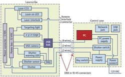
The major functional units in the Laserscribe system—including the laser, camera, x-y-z stages, and safety interlocks—are interfaced to a USB hub that relays data to and from the control case housing the PC controller (see Fig. 3). To enable the optical assembly to be moved in the x, y, and z directions, the Laserscribe unit incorporates three motorized stages from Zaber Technologies.
These stages each sport a stepper motor with a built-in controller that communicates via RS-232 protocol. The RS-232 signal is converted to USB signal using an in-line converter. While the x and y stages allow the system to pan across the area of interest, the z stage enables the camera to be focused directly onto the marker in the substrate.
The Laserscribe system employs two manually operated mechanisms that enable the operator to adjust the height of the z stage and the angle of the optics tube housing the laser and camera. The first is a gross vertical adjustment that allows adaptability to a variety of panel thicknesses, while the angular adjustment allows areas around the edges of the panel to be inspected (see Fig. 4).
Laser patterning
Before the system can be used, the operator must determine which area of the substrate needs to be patterned. The technician highlights the area using a black marker then uses a set of alignment tools to properly position a suction cup that will hold the head of the Laserscribe system to the target so the optics tube is in the general area of the marker.
The system is attached to the suction cup, the camera focused on the surface where the substrate is deposited, and the operator begins a preprogrammed search sequence. A search function in the software enables the user to automatically scan a 1 × 1-in. field for the marker and center it in the image. The operator can view the progress of the search on the screen located in the control case.
Once the marker has been found, the operator can draw one of several standard patterns at the desired location using the tools on the PC screen to identify the path that the laser beam spot should take (see Fig. 5). Having done so, the user then brings the laser into a standby mode and depresses the manual shutter switch inside the control case. After a processing time of a few seconds, the operator can view the pattern that has been made by examining images of it captured by the camera.
Since its introduction, the Laserscribe system has proved highly effective at producing new patterns in many multilayer panels. Its future may not be long-lived, however. As manufacturers continually improve the design, processes, and materials used to make such panels, the need to add more patterns to panels may eventually become a thing of the past.
Andrew Bodkin is president of Bodkin Design and Engineering (Newton, MA, USA; www.bodkindesign.com).
features, advantage, benefits
Bodkin Design and Engineering was asked to develop a portable imaging system combining a handheld patterning unit with a control subsystem that enables an operator to modify patterns on transparent panels after they have left the production line. Because the handheld Laserscribe system uses a laser that is not rated as eye-safe, it was important to factor safety into the design.
To alert personnel in the vicinity of the system that the laser is about to be deployed, a large LED lamp housed on the top of the unit is illuminated prior to activation of the laser.
The Laserscribe system also features a series of mechanical laser interlocks. One interlock housed on the outside of the unit allows the laser to operate only when the system has been fitted to the panel, ensuring that the laser cannot be inadvertently activated.
To guarantee that an operator is always present while the laser is operational, a mechanical shutter is positioned in the path of the laser. This shutter is only opened when a shutter switch on the control case housing the PC is manually depressed. A sensor on the shutter itself also detects the status of the shutter, providing an indication of whether the shutter is open or closed through a shutter warning LED.
Company Info
Bodkin Design and Engineering
www.bodkindesign.com
Cree
www.cree.com
PixeLINK
www.pixelink.com
Zaber Technologies
www.zaber.com
