3-D INSPECTION: Robots team with 3-D scanners for fast part profiling
In the aerospace and medical manufacturing industries, it is critical to inspect parts for random surface defects as nicks, scratches, dents, and pits. To determine if the part is to be rejected, precise information about the shape and the depth of each defect is required.
In many industries, defects as small as 100 µm in diameter and 25 µm in depth must be detected. Therefore, systems must have a spatial and depth resolution of 10 µm and 2.5 µm, respectively.
To evaluate these defects with such resolution and precision,3-D surface profilers are required. Although profilers operate at high resolution, their field of view tends to be small, resulting in a time-consuming inspection of parts with large surfaces. Since the inspection cycle time must not exceed the manufacturing cycle time, 3-D surface profilers alone are not fast enough to provide an adequate inspection solution for production environments.
However, defects will often be limited to a small number of areas on the part and can be detected visually using standard 2-D image analysis. After this is accomplished, a slower, more precise 3-D surface profiling technique can be used to determine the characteristics of these defects while at the same time increasing the throughput of the system.
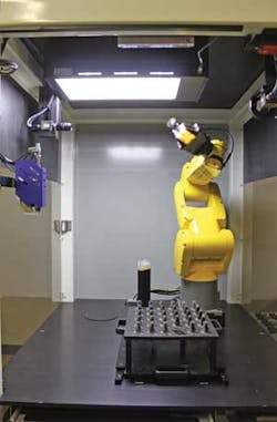
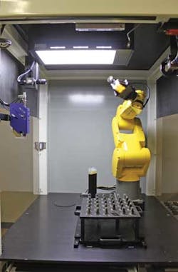
AV&R Vision & Robotics (Montreal, QC, Canada) has developed a system that combines visual inspection, robotics, and 3-D profiling techniques (see figure). Using a six-axis robot from Fanuc Robotics (Rochester Hills, MI, USA), parts are first presented to a 2448 × 2050-pixel GigE camera from Allied Vision Technologies (AVT; Stadtroda, Germany) that is fitted with a 50-mm focal length lens. After parts are positioned 0.5 m from the camera, images are captured and transferred to the host PC over the GigE interface. Thresholding, image filtering, and defect segmentation are performed using LabVIEW software from National Instruments (Austin, TX, USA).
AV&R Vision & Robotics has developed a system that combines visual inspection, robotics, and dimensional profiling techniques to inspect parts in 3-D.
Each time a suspicious area is found, it is located on the CAD model of the part and any 2-D image defects mapped onto the3-D CAD model. The transfer of this defect from the 2-D image to the 3-D CAD model gives the position of the defect in relation to the robot world coordinates.
The robot then automatically moves the part to present it in correct orientation at a distance of 65 mm from a 3-D surface profiler. Originally developed by the National Research Council of Canada (Montreal, QC, Canada;www.nrc-cnrc.gc.ca) and licensed to AV&R, the profiler uses laser triangulation to capture images of the part with a 3.5-µm depth resolution. After generating a 3-D point-cloud data set, Polyworks 3-D processing software from Innovmetric (Québec, QC, Canada) is used to characterize the defect and its severity.
By combining the strengths of visual and structured-light-based techniques, AV&R's system reduces the time required to inspect parts with large surfaces. While at present the system is used to inspect turbine airfoils, it can be adapted to inspect other parts such as tooling fixtures, automotive components, and metal housings. In the future, as 3-D scanners and profilers become faster and more powerful, it may be possible to use these devices to cover the full inspection requirements required by manufacturers of such components.

