SMART CAMERAS: Antisway crane system embeds smart camera
Port operators must ensure that the loading and unloading of cargo containers is performed efficiently. Although the ship-to-shore cranes employed in this process require skilled manual operators, the repetitive, time-consuming tasks can result in operator fatigue, which may lead to accidents that injure dock workers, damage cargo, and delay load handling.
To transfer cargo containers more quickly and safely, many port operators now require cranes to be equipped with automated sensing and control systems. They are designed to reduce the amount of sway induced by the motion of the crane's trolley that is used to move the hook to the correct position.
The crane's hook is attached to a spreader, which has a locking mechanism at each corner that attaches to the four corners of the container. After each container is attached to the spreader, it is lifted by the crane and moved either to or from the ship. Since this process will induce sway, a feedback mechanism is required to control the motion of the crane and reduce this effect.
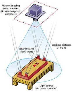
Microview & LinZhi Image Tech Corp. (MVLZ; Beijing, China) has developed an automated antisway system that incorporates a smart camera, fiber-optic communication link, and feedback control system based on a programmable logic controller (PLC; see Fig. 1).
To ensure the system can operate in inclement weather, near-infrared (NIR) markers are mounted onto the crane spreader. To image these markers, an Iris smart camera fromMatrox Imaging (Dorval, QC, Canada) is mounted on the crane's trolley. Because the working distance from the camera to the NIR markers is between 3 and 50 m, the camera is fitted with a 12-mm lens. This provides a viewing angle of 28°, allowing the spreader to always remain in the camera's field of view.
As the camera digitizes images of the markers, the center position of the tow markers is calculated in real time, providing an accurate position of the spreader. When the working distance from the camera to the spreader is 50 m, this allows the system to calculate the position of the spreader to within 10 mm. The data are then transferred over an RS-232 link from the camera to an RS-232 serial to fiber-optic data link.
Using this data link, the center position of the spreader is transferred to a remote fiber to RS-232 serial converter where it is interfaced to a PLC. This PLC is interfaced to an electronic control system that regulates the movement of the crane's trolley, effectively reducing any container sway that may occur.
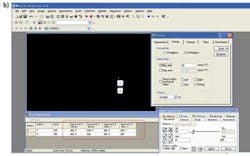
To digitize the position of the markers and calculate their center position, MVLZ used Matrox's Design Assistant that is bundled with the smart camera. This initialized the serial port on the camera, captured the raw image markers, performed blob analysis on the images, calculated the center position, and wrote the result to the serial port (see Fig. 2). According to Xing Xiao, technical support manager at MVLZ, the antisway system is now in use in port terminals in Zhenjiang and Haikou.


