Infrared lights spot glass-bottle flaws
By Andrew Wilson, Editor
Operators of large production facilities, such as those used in the manufacture of glass bottles, need to closely monitor production quality. For example, a central California manufacturer of wine bottles that produces more than 2 million bottles per day must track how many bottles are made, how many bottles are rejected, what types of defects are found, and how many bottles are finally packed for shipping.
Manufacturing defects can be identified at various assembly sites. At most sites, the bottle manufacturer currently uses photodetectors to count the bottles along the production line to determine the location and severity of any problems. For example, if a production line backs up due to a downstream problem, the new bottles being produced must be discarded. This situation results in bottles that are unaccounted for by the automated process and in unpredictable discrepancies between the number of bottles manufactured and those that are packed for shipping.
The bottle manufacturer had installed several machine-vision systems from suppliers such as Inex Vision Systems (Clearwater, FL, USA). These custom systems are used in an Ethernet-based networking environment to inspect each bottle produced and report statistical data to the corporate management information system. In this way, defective bottles can be correlated with the glass-molding process that builds them so that appropriate corrective actions can be made.
Even with these machine-vision systems in place, however, the bottle manufacturer decided to install additional machine-vision systems that could count the number of bottles as they pass along the production line. The existing system, which used a photodetector to count bottles, proved useful only where bottles moved in a single file.
A new machine-vision counter was desired that could be suspended above the bottle conveyor belt in situations where bulk-conveying techniques were in place and could count multiple bottles simultaneously. To fulfill these requirements, the bottle manufacturer called upon Saber Engineering (Auburn, CA, USA), a company that has installed industrial automation, inspection, and control systems in national production facilities. According to Brian Thomas, principal engineer at Saber Engineering, the company has built and installed numerous machine-vision systems that interface with programmable logic controllers, human-machine-interface (HMI) software packages, and networking standards such as Ethernet.
Bottle lighting
"A major challenge in developing this machine-vision system," Thomas says, "is imaging transparent bottles as they move along a reflective-metal conveyor belt." In addition to imaging bottles of different thicknesses and colors, the system must also operate in an environment where powerful fluorescent factory lights produce glare along the metal conveyor.
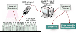
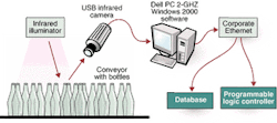
FIGURE 1. A combination of off-the-shelf illumination systems, cameras, and proprietary software is used to overcome a hostile factory-lighting environment. Infrared light-emitting diode light sources are placed behind a Logitech Pro 4000 USB camera, which images the bottles as they pass along a conveyor belt.
null
To overcome this challenge, Thomas and his colleagues used an infrared (IR) light-emitting-diode (LED) light source. They positioned 72 IR LEDs in a rectangular format; two of these IR light sources were placed behind a Pro 4000 USB camera from Logitech (Fremont, CA, USA) located above the conveyor belt (see Fig. 1). "This diffuse light source reduces the spectral reflections from the conveyor belt and the glass bottles," says Thomas. "In addition, the fluorescent light emanating from the factory lights can be eliminated by using an IR pass filter in front of the camera," he adds. Infrared imaging also substantially reduces the reflective effects of varying glass colors from different bottle types.
The supplied Pro 4000 USB camera was modified by Saber Engineering to remove the IR cut-off filter. Because the working distance varies from the tops of the bottles, the camera was fitted with a 6-mm C-mount lens from Fujinon (Wayne, NJ, USA) and an IR pass filter from Edmund Industrial Optics (Barrington, NJ, USA). In addition, the camera was housed in an aluminum industrial enclosure with a C-mount adapter.
"Although the camera is specified as producing 640 × 480 × 24-bit images at 30 frames/s," says Thomas, "in practice, only about 15 frames/s can be achieved over the USB 1.1 interface bus." Operating at these data rates, the images are transferred across the USB bus to the host memory of a 2-GHz PC from Dell Computer (Round Rock, TX, USA) running Windows 2000. The computer uses several software functions to count the bottles as they pass under the camera system.
Software design
In the system software design, Kevin Supinger, senior software engineer at Saber Engineering, took advantage of the features of the Microsoft DirectX suite of multimedia application programming interfaces (APIs) built into a Windows environment. "DirectX provides a standard development platform for Windows-based PCs that enables software developers to access specialized hardware features without having to write hardware-specific code," says Supinger. "At the core of DirectX are APIs that control low-level functions such as video control," he adds. Also, the modularity of DirectShow allows dynamic or preconfigured filters to be arranged for flexibility. The video-processing chain is supported by the FilterGraph Manager.
Although the software works with FireWire (IEEE 1394), frame grabbers, and USB 2.0, the USB camera was chosen because a frame grabber was built into the camera and therefore is not subject to analog noise generated by the harsh electrical environment. The desired cable length of 48 ft was easily achieved. Moreover, USB was built into the computer motherboard, and the video frame format supported YUV planar instead of interleaved pixels like FireWire.
As images are captured by the Pro 4000 USB camera, they are presented in DirectX as a stream of image buffers that must be processed as they arrive. To detect the presence of bottles within the images, several different algorithms are applied to the image buffers.
"Because the whole detection process needed to be accomplished in less than 20 ms," says Supinger, "we could not take advantage of off-the-shelf software from companies such as Matrox Imaging (Dorval, QC, Canada) and Data Translation (Marlboro, MA, USA)." Instead, the derived algorithm, which is divided into three major parts—edge detector, circle finder, and image tracker—is written in C++ using Microsoft's Visual Studio and recoded in assembler to speed image processing. This software design also takes advantage of the Intel MMX instruction set.
To determine whether a bottle can be detected within the image, the algorithm first performs an iterative edge-detection and thinning technique across the image buffer (see Fig. 2). This algorithm is performed across the 640 × 480 × 8-bit luminance image in approximately 2 ms running on the 2-GHz PC. After the edges have been determined and thinned, the buffer containing the edge-detection data is presented to the circle-finder filter. Here, a self-tuning Hough transform, written in assembler, looks for circles (representing the tops of the bottles) within the edges.
FIGURE 2. To determine whether a bottle is detected in an image, software algorithms perform an iterative edge-detection technique across the image buffer. After the edges have been determined, the buffer-contained edge-detection data are presented to a circle-finder filter. A Hough transform written in assembler looks for circles within the edges, which represent the tops of the bottles.
null
"After the circles have been determined, the circle finder passes on a scalable-vector-graphics document that defines the discovered objects. This document is based on extensible markup language," explains Supinger. After the circle finder has successfully found the imaged bottles, the information is delivered to the image tracker. The tracked data are then laid over the original video data to provide visual information for the system operator.
The complete code for the vision application is developed as an object linking and embedding custom control (OCX) independent program module that can be integrated by other programs in a Windows environment, such as Visual Basic or Visual C++. The OCX can also be used in Intellution (Foxborough, MA, USA), Wonderware (Lake Forest, CA, USA), and other HMI automation software. This control comes with a specific list of methods, properties, and events. Whereas properties define the way the control is set up, events represent the output that the OCX generates. During operation, information from the control is received by event notifications from the OCX in a Visual Basic or Visual C++ application. The application or user interface is responsible for maintaining the count and presenting the count to the automation system or database.
"By decoupling the vision-system output with its algorithm detail," says Supinger, "we were able to write an application that easily interfaced the image-processing program with the customer's data requirements." In this way, the user-interface application program could be used to receive information about bottles being counted and transfer that information using Microsoft ActiveX Data Objects across an Ethernet network. Also, when bottle shapes changed, other algorithms could be easily substituted automatically.
Application interface
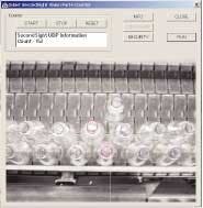
As bottles move from left to right along the production line, the camera images them, and the tracked images appear on the system PC monitor. As bottles cross the yellow line displayed in the middle of image, they are counted by the machine-vision system and assigned a number.
null
As the bottles move from left to right along the production line, the camera images them, and the tracked images appear on the PC monitor (see photo [above]). As the bottles cross the yellow line displayed in the middle of the image, they are counted by the machine-vision system and assigned a number. Should the manufacturing production line become backed up, the bottles can then move from right to left across the images. In such cases, the bottles are not recounted and the system operator is notified of this condition.
"In the future," says Thomas, "the machine-vision software will likely be modified so that bottle motion down the production line proceeds at an adjusted rate." Because information derived from the vision system determines the number of bottles traveling down the production line, this information could be used to control the speed of the conveyor belts. Therefore, if the system backs up, the upstream conveyor belt speed is slowed down. If too few bottles are detected, the belt speed could be increased.
Providing live streaming video across a number of intelligent monitors already installed at the production facility could also be easily accomplished, according to Thomas. "Because the facility has several Ethernet-based Intellution Dynamics systems in place," says Thomas, "vision data could be passed over the Ethernet from the vision system to these terminals." This would allow different system operators to visually monitor the production environment along the production line and diagnose line-backup problems.
Company Info
Data Translation www.datx.com
Dell Computer www.dell.com
Edmund Industrial Optics www.edmundoptics.com
Fujinon Inc. www.fujinon.com
Inex Vision Systems www.inexvision.com
Intellution www.gefanucautomation.com
Logitech Inc. www.logitech.com
Matrox Imaging www.matrox.com/imaging
Saber Engineering www.sabereng.com


