CCD camera finds microdisplay defects
By C. G. Masi, Contributing Editor
Inspecting microdisplays the size of postage stamps, whose images will be magnified to several feet across, requires searching for flaws as small as tens of microns. Production testing of these tiny microdisplays is clearly an inspection task for a machine-vision system. There is no other cost-effective or efficient way to manually inspect microdisplays, even with a microscope, because many display tests involve photometric or colorimetric measurements.
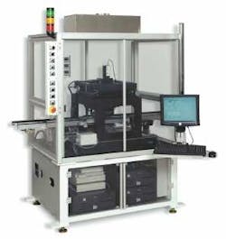
When Mike Wilson, product manager of microdisplay test systems at Westar Display Technologies (St. Charles, MO), was contracted to design an inspection system to test microdisplays for the US Display Consortium (San Jose, CA), he knew the project would include machine-vision technology, as well as robotic-handler, photometric-measurement, and systems-integration components. Wilson designed the microdisplay inspection system (MDIS) to test liquid-crystal-on-silicon (LCOS) reflective displays, which form images by reflecting light from some parts of a display and blocking it at others (see Fig. 1).
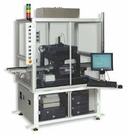
FIGURE 1. MDIS incorporates a robotic handler, an optical system mounted on a gantry, and three instruments: a CCD camera, a photomultiplier tube, and a spectrophotometer. The handler's programmable logic controller communicates with the overall system host, which is a standard desktop PC. Two additional PCs analyze the images of one display under test while the inspection system takes data from the next display. A forced-air purge keep particulates away from the display under test. photo: Westar Display Technologies
A LCOS display typically measures 0.7 in. (18 mm) to 0.9 in. (23 mm) along the diagonal. During production, the display starts as a silicon chip covered with small aluminum electrodes (on the order of 10 to 12 µm across) that act as mirrors. The manufacturer adds a liquid-crystal layer on top of the chip and tops that with a cover glass. The displays are packaged with a flex-circuit tail that interconnects to the drive electronics in the end application.
null
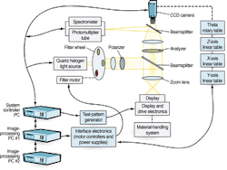
The MDIS makes optical performance tests and inspects for defects (see Fig. 2). Optical-performance tests include measuring the display's reflectance, uniformity, contrast ratio, color, and other parameters. Defect-inspection tests include pixel outs, pixels stuck bright, scratches, and other qualitative defects. For optical measurements, the test system includes a spectrometer and a photomultiplier tube (PMT) coupled to the system through optical fiber. A CCD camera performs the defect measurements.
A test enclosure, complete with a forced clean-air purge and filters, keeps particulates away from the display under test (DUT). A programmable logic controller coordinates the movements of the robotic handler.
The microdisplays arrive at the test station active-side up on stamped stainless-steel process trays via an edge-belt conveyor. Process trays carry five displays each, fitted into wells. Rectangular holes cut into the well bottoms provide access for a vacuum chuck to lift the display up out of the well without contacting the display's active surface. In fact, three vacuum chucks are used to lift the display slightly out of the tray. Two vacuum chucks preheat the parts to normal operating temperatures of 45°C to 60°C. The third chuck maintains that temperature and presents the part to the optical system, while a prober assembly contacts the flex-circuit terminals.
All of the inspection system's optical sensors look through one lens. The optical system starts with a quartz halogen light source coupled to optics via a fiber bundle; the light then passes through a filter wheel and a polarizer. The now polarized light reflects from a beamsplitter through a zoom-lens assembly to illuminate the display.
Light reflecting from the display goes back up through the beamsplitter to an analyzer, which forms an image by blocking unrotated light. This image goes up to the CCD camera and spectrometer through a second beamsplitter.
Inspection procedure
The first inspection step is to roughly position the display. Then, the test system looks for the display's edges to do a fine alignment. A commercial test-pattern generator drives the display from white to black. The inspection system then finds the edges of the area that exhibit change. It then drives an x, y, θ motion table to move the optical assembly into position over the display.
In the next inspection step, a USB 2000 grating spectrophotometer manufactured by Ocean Optics (Dunedin, FL) measures the display's reflectance, uniformity, and contrast. The test protocol calls for spot readings at multiple points over the display area. Each reading spot covers several hundred pixels. How many spots the MDIS checks depends on the display manufacturer's specification, but nine points are typical.
Westar's Wilson mounted the optical system on a gantry over the DUT so that it can be moved while the DUT stays stationary. The fibers from the spectrometer just look into the middle of the lens field of view.
The system uses a PMT to measure switching speed and flicker. "Minimizing flicker requires an adjustment of the drive voltage, and sometimes that can vary from display to display," says Wilson. "So, depending upon the requirements of the production process, it may be beneficial to adjust those on each display before starting the test." Wilson chose a PMT manufactured by Hamamatsu (Hamamatsu City, Japan) because his company was already using it in another instrument developed for testing direct-view flat-panel displays.
After the optical measurements, the test system scans for defects using a Retiga 1300 monochrome CCD camera from QImaging (Vancouver, BC, Canada). The camera's array contains 1300 × 1030 pixels, but the effective resolution coming out of the interface is 1280 × 1024 pixels. It provides a 12-bit gray-level resolution and a FireWire interface.
For defect tests, the system uses the CCD camera to tile multiple images across the display surface. To find tiny defects it needs to examine at relatively high resolution, typically nine CCD pixels per display pixel. These images go over the FireWire interface to the imaging computer, which consists of two commercial off-the-shelf PCs in a parallel-processing architecture. A third PC orchestrates the test, collects data from the optical measurements, and steers the optics over the display.
Image processing is compute-intensive, so the additional PCs process images while the MDIS tests the next display. All three Dell Computer (Round Rock, TX) computers contain 2-GHz Pentium 4 processors running Windows 2000.
The system software comprises two applications. One provides a manual-control interface that just allows a technician to manually drive the test equipment and tests. The other allows test engineers to develop fully automated tests.
null
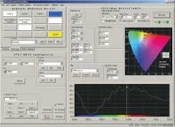
Through the manual control interface, the technician can directly move the camera over the display under test (see Fig. 3). The interface consists of a large screen that is organized into three areas. The DUT control area allows the technician to control the test patterns on the display. Another area provides motion control, allowing the technician to reposition the optical system over the display. The third area is the instrument interface, which provides access to the spectrometer, PMT, and CCD camera.
The automated test sequencer is built around TestStand Test Executive software from National Instruments (Austin, TX). The test sequencer makes it possible to write a test sequence that can automatically operate the system, take the required data, and use those data to make pass/fail decisions. The software also provides access to a library of test algorithms and the capability to string them together to create test scripts. These analysis algorithms use the Halcon image-processing library from MVTec (Munich, Germany).
The test sequence can run unassisted. The robotic handler feeds the trays into the test system. In turn, the test system processes the parts, logs the results to a database, and delivers the trays out the other end. The database stores test results by serial number, making it available to downstream equipment to bin the good parts and reject the bad parts.
Company Information
Dell Computer Corp.
Round Rock, TX, USA
www.dell.com
Hamamatsu
Hamamatsu City, Japan
www.city.hamamatsu.shizuoka.jp
MVTec
Munich, Germany
www.mvtec.com
National Instruments
Austin, TX, USA
www.ni.com
Ocean Optics
Dunedin, FL, USA
www.oceanoptics.com
QImaging
Vancouver, BC, Canada
www.qimaging.com
US Display Consortium
San Jose, CA, USA
www.usdc.org
Westar Display Technologies
St. Charles, MO, USA
www.wastar.com


