Seeing Red
Choosing an infrared camera requires an understanding of both IR detector technology and the nature of each application
Esoteric semiconductor materials such as indium gallium arsenide (InGaAs) and mercury cadmium telluride (HgCdTe or MCT) are expensive and require complex fabrication, readout circuitry, and lenses. As a result, infrared (IR) cameras have been limited to applications such as military, security, and electrical inspection. While the cost of the sensors used in cameras may be an order of magnitude or more higher than the CCDs and CMOS imagers used in visible-light cameras, government restrictions limiting the export of IR cameras has also led to limited acceptance. Despite this, a number of developments in both sensor technology and camera development over the past few years promises to lower the cost of these cameras, making them more attractive for machine-vision applications.
Like the visible camera market, where there are a handful of CCD and CMOS vendors—notably Sony, Kodak, and Micron Technology—IR camera developers are also limited in their choice of imagers. Here, however, the similarity ends, since IR designers can choose from a number of different technologies with which to build their products. These include devices based on thermal sensors such as microbolometers fabricated from amorphous silicon or vanadium oxide (VO2) and photonic sensors based on germanium, InGaAs, and HgCdTe.
Microbolometer-based cameras
Thermal imagers, such as microbolometers, are frequency-independent detectors that change their temperature in response to absorbed energy. Photonic devices, on the other hand, can detect specific frequencies across the IR spectrum and are faster and more sensitive than their microbolometer counterparts. Detecting thermal energy over the 7—14-µm region of the spectrum makes low-cost bolometer-based cameras useful in applications such as visualizing objects through smoke, smog, and dust.
Microbolometer-based cameras such as the long-wavelength, passive infrared core from Infrared Inc., for example, target these applications using an amorphous silicon microbolometer from L-3 Communications. With a 30-µm, 160 × 120-pixel array, the camera core can capture images at rates of 30 (NTSC) or 25 (PAL) frames/s. VO2-based cameras such as the ThermaCAM EX300 from FLIR Systems have similar features offering a 320 × 240-pixel array that can be read out at NTSC frame rates. Rather than offer an OEM camera module, FLIR has targeted the ThermaCAM toward end users incorporating an in-built LCD display and a laser locator to help users associate the IR image displayed on the LCD with the target image. Other companies such as Jenoptik are also targeting the 7.5–14-µm spectral range with products such as the IR-TM 384 IR camera. Designed for the machine-vision market, the 384 × 288-pixel microbolometer-based camera features a FireWire, VGA, or optional GigE interface.
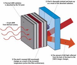
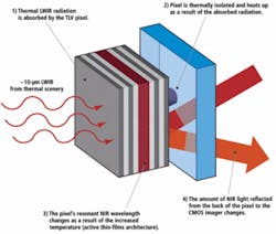
However, because microbolometer sensors are manufactured using a microelectromechanical-system process, a custom foundry with specialized amorphous silicon or VO2 processing capability is required to produce them. Looking to alleviate this somewhat costly process, Redshift Systems has developed what the company calls an optical thermal light valve (TLV)—essentially a tunable filter composed of an array of pixels on an optically reflective and thermally conductive substrate (see Fig. 1).
As LWIR radiation from the scene is imaged onto and absorbed by the TLV, the pixels on the array are heated in direct relation to the thermal signature of the scene. As this occurs, the minimum reflective wavelengths of the pixels shift based upon the incident thermal energy. A narrowband near-IR source then scans the temperature of the pixels across the TLV reflecting near-IR from the TLV in varying amounts, depending on the pixel temperature, onto a CMOS imager.
In this manner, a thermal image of the scene is produced. To commercialize this technology, Redshift offers its OpTIC optical thermal imaging camera engines—subsystems that can be integrated into an OEM IR camera line. Each OpTIC engine contains a TLV filter, optics, and interface electronics. First in the series is the OpTIC 1080 engine that features an 80 × 60-pixel array.
Visible and SWIR
In many machine-vision applications there is a requirement to display both visible and infrared images. While such systems can use two independent detectors or cameras, a more-effective approach is to combine both visible and IR detection using a single image sensor. While the visible spectrum extends from approximately 0.4 to 0.7 µm, wavelengths longer than these are often imaged by dedicated sensors such as InGaAs- or MCT-based detectors.
Over the past five years, however, developments in InGaAs technology have allowed manufacturers such as FLIR and Goodrich to offer VisGaAs and Visible-InGaAs, respectively. In 2003, Indigo Systems (now FLIR) developed a method for processing standard InGaAs detector material that enhances the short-wavelength spectral response. Dubbed VisGaAs, devices fabricated using this material allow visible and near-IR imaging to be performed on a single focal plane array (FPA). Operating in a range from 400 to 1700 nm, the technology has been used in FLIR’s HS camera series that is available with a 320 × 256 or 640 × 512 FPA (see Fig. 2). Goodrich’s SU320KTSVis-1.7RT also provides a 0.4—1.7-μm response and simultaneous RS-170 and Camera Link outputs.
NoblePeak Vision recently introduced its 744 × 576 TriWave (visible, near-IR, and SWIR) sensor technology that integrates germanium photodetectors on a monolithic readout IC using a CMOS process (see Vision Systems Design, May 2008, p. 26). Unlike InGaAs sensors that require flip-chip bonded read-out ICs, read-out electronics are integrated into the same monolithic IC to reduce the cost. NoblePeak Vision has already demonstrated the device in a prototype camera system that achieves sensitivity to wavelengths from 0.4 to 1.65 µm and will sell the complete camera core with which OEMs can build their own cameras.
Beyond SWIR
For special applications, where high-speed, and improved sensitivity are required, cooled photodetector arrays are used in IR cameras. These devices are based on materials that include indium antinomide (InSb) for MWIR applications, HgCdTe for MWIR and LWIR applications, and QWIP (quantum-well infrared photodetector) devices for more specialized frequency-specific applications. These devices exhibit different spectral-response curves and detector sensitivities and often target applications in the 3–5-µm (MWIR) and 8–12-µm (LWIR) spectrums.
To determine the spectral sensitivity of a specific IR camera, the noise equivalent temperature difference (NETD) must be known. NETD is a measure of the uncertainty that occurs when a specific temperature is measured and is given in millikelvins (mK). Obviously, the lower this figure, the more sensitive the detector will be. This figure depends on, among other factors, the detector noise, system noise, and the size of the lens aperture used in the camera (see “Choosing a lens for an IR camera,” p. 69). Typically uncooled bolometer detectors are specified with an NETD of between 80 and 200 mK, while cooled photon IR HgCdTe detectors (LWIR or MWIR) or InSb (MWIR) can approach a NETD figure of 10 mK.
Infrared Inc.’s M-Wave InSb MWIR camera, for example, uses a cooled InSb detector with less than 15 mK NETD to capture images in the 1.5–5.5-µm range. With a 320 × 256 InSb FPA and 30-µm pixel size, the camera features snapshot exposure and offers both analog and simultaneous 14-bit digital output. Similarly, the Titanium 550 IR camera from Electrophysics incorporates a 320 × 256 InSb infrared FPA to image the 3.6—5.1-µm spectrum. The camera features a 380-frame/s output rate and a uses a closed-cycle Sterling cooler to achieve a typical thermal sensitivity of 15 mK. In addition, a 1.5- to 5-μm version is available.
While uncooled microbolometer-based IR cameras provide affordable solutions for many applications, higher-performance IR imaging applications require the higher sensitivity of cooled MCT-based cameras. For example, while the XPORT camera from XenICs uses a microbolometer array to achieve 384 × 288-pixel resolution at video rates, its NETD over the 8–14-µm range is less than 150 mK. The CMT 256 LWIR camera from Thermosensorik, however, uses a cooled 256 × 256 MCT detector to achieve a maximum 880-frame/s data rate and a spectral sensitivity of less than 20 mK.
Dual-band QWIPs
To reduce the high cost and low yield associated with MCT detectors, many companies have turned their attention to developing quantum-well infrared photodetectors. These devices use GaAs growth and process technology. For the military, the lower cost of such devices combined with their ability to discern more than one frequency spectrum with the same device is especially useful in applications that previously required two IR cameras.
In 2003, QmagiQ offered commercially available QWIP FPAs, the first of which was a small-format 320 × 256 LWIR imaging array. A joint program involving QmagiQ and FLIR led to the development of a small-format MWIR FPA and a dual-band or two-color (MWIR/LWIR) FPA. The resulting two-color device contains a 320 × 256-pixel array of spatially registered dual-wavelength detectors to absorb in the 4–5- and 8–9-µm spectral ranges, respectively.
Such dual-color QWIPs are now being used in a number of different cameras. At the 2007 Defense & Security Symposium, IRCAM introduced a series of cameras based on QWIP technology. The company’s Geminis, for example, is a cooled 110k ML Pro QWIP-based camera that features a 384 × 288-pixel array and operates at frequencies of 4.4—5.5 µm (MWIR) and 7.8—8.8 µm (LWIR). With a Camera Link interface, the camera supports data rates up to 130 Mbytes/s and is targeted toward high-speed IR imaging applications.
Thermosensorik also uses a dual-band QWIP in its QWIP 384 dual-band IR camera that can capture images in both 4.4–5.4-µm (MWIR) and 7.8–8.8-µm (LWIR) spectral ranges. The camera uses a Sterling cooler to achieve a spectral sensitivity of less than 25 mK (see Fig. 3).
Researchers are currently studying other types of detectors—most notably quantum-dot infrared photodetectors (QDIPs). While QWIP-based cameras do not absorb much light at normal incidence, QDIPs do allow for absorption of normal-incidence light.
Four years ago, researchers from Northwestern University, the Air Force Research Laboratory, and the Missile Defense Agency fabricated and tested the first QDIP FPA (see Laser Focus World, May 2005; www.laserfocusworld.com/articles/232486/). According to QmagiQ, such devices theoretically offer higher sensitivity and higher operating temperature than QWIPs at comparable or lower cost.
Choosing a lens for an IR camera
Each of the three major wavebands in the IR—SWIR, MWIR, LWIR—uses a number of different detectors to convert incoming IR radiation to visible images. In choosing a lens for IR cameras, many of the specifications that must be considered are identical to those for choosing a lens for a visible-wavelength camera, including the field of view, the aperture required, and whether the lens should be fixed focal length, zoom, or telecentric.
Since the standards employed in cameras used for the visible spectrum have not been fully adopted in the IR spectrum, the format (or the size of the detector array) can vary from camera to camera. When determining field of view, or effective focal length, the system integrator must ensure that the lens is designed for the format of the camera. If no such lenses are readily available, the lens must have a larger-format design (or image circle) than the camera. If this image circle is smaller than the camera format, lens vignetting effects will occur.
If the detector technology used in the camera requires cooling, other considerations must also be taken into consideration. Most InSb cameras operating in the 3—5-μm range require a cold stop physically located inside the camera to block heat from entering the camera. From an optical perspective, lenses for these cameras must be designed so that the stop of the lens coincides with the location of the cold stop. This affects the lens design, since it is preferable to place the stop in the center of the lens and provide an iris at the stop location.
However, in cooled cameras, the stop is moved behind the lens, and, except in special cases, there are no provisions made for an iris. Thus, no unwanted noise can pass through the stop and degrade the dynamic range of the camera. In cooled cameras, the location of the cold stop must be properly matched to the FPA.
In the LWIR region where most materials absorb energy greater than 10 μm in wavelength, transmission number or “t-number” also becomes important. This provides developers with the amount of energy that is transmitted by the lens. Obviously, the higher this percentage the greater the transmission throughput and it is not uncommon to see lenses with from 80%—92% transmission percentages.
JONATHAN S. KANE is president of Computer Optics (Hudson, NH, USA; www.computeroptics.com), a company specializing in the design of IR zoom lenses in the SWIR, MWIR, and LWIR spectra.


