Types of machine vision systems
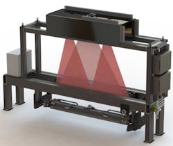
Vision systems can operate in one or multiple dimensions. 1D vision systems analyze the digital signal one line at a time instead of looking at an entire picture. These systems generally look for the variance between the previous and following acquired lines. One of the most common applications for 1D machine vision is to detect and classify defects on materials manufactured in a continuous process such as paper, metals, plastics, and non-wovens.
2D vision systems provide area scans that work well for discrete parts. These systems are compatible with most software packages and are the default technology used for most machine vision applications. 2D systems are available in a continually-expanding range of resolutions. Mainstream, general-purpose applications usually feature resolutions with an upper limit of around 5 MPixels. Camera sensors in 10, 20, or 30 MPixels and above are becoming part of standard 2D product lineups, however. Speed, cost, and related optics differentiate the available resolutions.
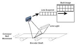
Where a 2D area array system takes a two-dimensional snapshot of an object, 2D line scan systems build images line-by-line. A good analogy to understand the difference between area scan and line scan systems is to consider the difference between photocopiers, and fax machines or scanners.
The photocopier is like an area array camera. It needs to see the entire document to copy the picture. Because there is no motion and since they need to see the full document, copiers tend to be quite large. A fax machine or document scanner, however, can sit on a desk. These devices are akin to line scan cameras, scanning documents line by line to create an electronic copy of the documents.
Line scan machine vision systems require motion, just as a fax machine or scanner require that a document be fed through the machine such that the scanner can read the document line-by-line and use that data to build the document in memory.
Line scan cameras are not smaller than area scan cameras. They are often deployed on machine vision systems with tight space constraints, however. Line scan systems are frequently used to inspect cylindrical objects, to meet high-resolution and/or high-speed inspection requirements, and to inspect objects in continuous motion. Line scan cameras tend to be less expensive, though a bit more complicated to integrate into a system due to the encoder feedback required. Line scan cameras also require intense illumination.
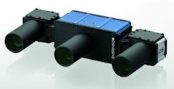
There are several varieties of 3D machine vision systems. Stereo systems capture 3D information by using two cameras displaced horizontally from one another. Each camera images slightly different projections of the object being viewed. It is then possible to match a set of points in one image with the same set of points in the second image – a task known as the correspondence problem.
By comparing these two images, relative depth information can then be computed and represented in the form of a disparity map. In this map, objects that are closer to the stereo camera system will have a larger disparity than those that are further away.
Before such 3D depth information can be accurately obtained it is necessary to calibrate the stereo imaging system. Any lens distortion will adversely affect the computed result. Because of this, most manufacturers that supply these passive stereo systems offer some form of calibration charts and/or software to perform this task.
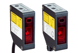
3D laser displacement sensors employ line lasers and single cameras to generate a 3D profile of the object being imaged. A laser line is projected across the object and the reflected light is captured by a camera. A depth map or surface profile can be calculated by measuring the displacement of the reflected laser line across the image.
While such structured-light-based systems are useful they require the camera system and laser light projector, or more commonly the object to be imaged, to move across the field of view of the system. In addition, where shiny specular surfaces need to be imaged, structured-light-based systems may not prove effective.
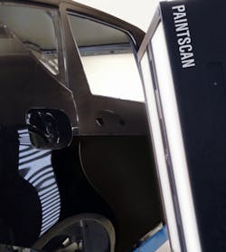
To overcome these limitations, a technique known as fringe pattern analysis can be implemented. In this technique, a series of intensity patterns with shifting periods is projected across the object to be imaged. Phase-shifted images reflected from the object are then captured by a camera and the relative phase map or measurement of the local slope at every point in the object is calculated. From this phase map, 3D coordinate information can be determined.
