Icing wind tunnel research employs 3D, thermal, and high-speed vision systems
Multiple vision systems at Iowa State University’s (Ames, Iowa, USA: www.iastate.edu) Icing Research Tunnel assist in the study of ice accretion, research that can lead to safer aircraft travel and more dependable and efficient wind power generation.
The Aircraft Icing Physics and Anti/De-icing Technology Laboratory, led by Dr. Hui Hu, a professor in aerospace engineering at Iowa State University, uses a 3D imaging system, infrared camera system, and high-speed camera system to study the formation of ice crystals on airplane wings, wind turbine blades, and power cables, and discover how to prevent or delay the ice from forming.
The tunnel, donated to the university in 2010 by the Goodrich Corporation, now UTC Aerospace systems (Charlotte, NC, USA; https://utcaerospacesystems.com/), and refurbished in 2014, can create a maximum wind speed of 100 m/s (224 mph) and an air temperature down to -25° C. The size of the water droplets and the liquid water content are also variable, allowing the research team to study different varieties of ice like glaze ice (freezing rain) and rime ice (formed in cold and dry conditions).
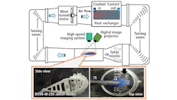
Model aircraft wings, wind turbine props, or other test subjects are placed in a 2 m long, 400 mm high, 400 mm wide test section and hit with cold air blasts and moisture that form ice on the test object. Dr. Hu’s team analyzes the data gathered from the test chamber with custom image processing software developed in C++ and running on a Dell (Round Rock, TX, USA; www.dell.com) Precision 3620 PC.
In the 2018 research paper, An experimental investigation on the unsteady heat transfer process over an ice accreting airfoil surface, (http://bit.ly/VSD-ICE) the lab utilized high speed and thermal imaging technology to study surface temperature distribution over a 3D printed airfoil/wing model as ice accreted over its surface. A FLIR (Wilsonville, OR, USA; www.flir.com) A615 camera with 640 x 480 pixel resolution and GigE Vision interface, running at 200 fps, was mounted 350 mm above the airfoil model and observed the model through an IR transmission window.
In a 2019 research paper, titled Quantification of 3D ice structures accreted on a wind turbine airfoil model, (http://bit.ly/VSD-ICE1), Dr. Hu’s team utilized two vision systems. The first was a high-resolution system that utilized a PCO (Kelheim, Germany; www.pco.de) Dimax HD Camera at 2000 x 2000 resolution, with a Nikon (Tokyo, Japan; www.nikon.com) 60 mm Nikkor 2.8D lens, and 150 W fiber-coupled halogen lights.
The second vision system, the Digital Imaging Projection (DIP) 3D scanning system, captured the shapes of the ice structures formed during the experiment using structured light, a technique like stereo vision that replaces one camera with a digital projector to project a digital image with known pattern characteristics onto the model. Measurements were taken to generate 3D models of the shapes formed over the progression of the experiment, showing the increasing amount of ice. 3D data from the system was used to 3D print models of the ice geometry that formed over the wing surfaces
This story was originally printed in the November/December 2019 issue of Vision Systems Design magazine.
About the Author

Dennis Scimeca
Dennis Scimeca is a veteran technology journalist with expertise in interactive entertainment and virtual reality. At Vision Systems Design, Dennis covered machine vision and image processing with an eye toward leading-edge technologies and practical applications for making a better world. Currently, he is the senior editor for technology at IndustryWeek, a partner publication to Vision Systems Design.
