Automated system inspects radioactive medical imaging product labels
In nuclear medical imaging, small amounts of radioactive materials called imaging agents (or radiotracers) are injected into the bloodstream, inhaled, or swallowed. In a magnetic resonance imaging (MRI) system, for example, gadolinium may be given to a person to highlight areas of tumor or inflammation.
For providers of these radiotracers, inspection of the labels represents an early and crucial part of the process to ensure that an incorrect agent is not administered to a patient. At one large provider of radioactive medical imaging products, the previous manual process uses a label rewind table to unroll labels, where a person looks at each one to ensure proper printing to identify the various fields on the label: calibration date, calibration time, lot number, concentration, volume, and expiration date. This process proved time consuming, inefficient, and prone to costly mistakes.
Seeking an automated, repeatable, and accurate process, the company contacted systems integration company Artemis Vision (Denver, CO, USA; www.artemisvision.com).
“A lot of scrutiny and regulatory requirements exist when dealing with these substances,” says Tom Brennan, President, Artemis Vision. “Such companies get audited by the FDA, so they wanted something more repeatable than a person looking at the labels.”
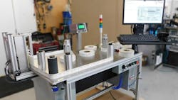
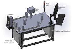
In the new system (Figure 1), an operator opens up a label recipe on the human-machine interface (HMI), loads a roll of labels on a label rewind table from Web Techniques (Fenton, MO, USA; www.webtechniquesinc.com) and strings it through a series of rollers in front of a KD6R309MX contact image sensor (CIS) line scan camera from Mitsubishi Electric Corporation (Tokyo, Japan; www.mitsubishielectric.com). Offering a 309.7 mm scan width, the camera features a Camera Link interface, built-in white LEDs, and a 7,296-pixel array.
After starting the table, the labels reel from one side of the table to the other, passing by the line scan camera for visual inspection. Images are processed by HALCON machine vision software from MVTec (Munich, Germany; www.mvtec.com) that verifies the fields on the label with optical character recognition (OCR) and optical character verification (OCV) tools. Additionally, a neural network running in the TensorFlow (www.tensorflow.org) open-source software library checks for smudging, tears, and wrinkles.
Processing is done on a Nuvo-5000 industrial PC from Neousys Technology (New Taipei City, Taiwan; www.neousys-tech.com), which features an Intel 6th gen core CPU processor and a Grablink Full Camera Link frame grabber from Euresys (Angleur, Belgium; www.euresys.com). Neural network training for the smudge, tear, and wrinkle detection in the TensorFlow framework is done on a graphics processing unit (GPU) from NVIDIA (Santa Clara, CA, USA; www.nvidia.com).
To inspect the key printed items, the most important algorithm is a pattern matching algorithm on a specific part of the label to register all the other inspections, to make sure OCR takes place in the right location on the label, according to Brennan. If a label passes, the table continues to run at a speed of about 1 label/s. If a label fails, the table automatically stops, a red light turns on, and a position is defined for the operator to remove the label. When this happens, the operator marks the rejection down on a sheet of paper, initials it, and starts the table again to continue the inspection process.
In terms of hardware choices for the system, the CIS line scan camera provided Brennan with crisp edges on the characters, which is paramount when performing OCR and OCV applications.
“Because the CIS line scan camera uses a rod lens array, we get incredible imaging performance in terms of the contrast and the crispness of the edges of the characters,” he says. “Using a normal area scan camera and lens results in a certain amount of blur and fuzz on the edges of the characters. Even if it’s just a few pixels, this can be problematic in OCR, because a few pixels of fuzziness around the character can easily make a 6 look like 8, for example.”
The camera offers 600 dpi resolution and 12-inch field of view, resulting in a minimum defect size of around two or three printing pixels in size, says Brennan.
A through-beam photoeye from Web Techniques detects each label to transition between label rolls, and the label rewind table (Figure 2) is run by a PLC and variable frequency drive from Mitsubishi Electric and an incremental rotary encoder from Datalogic (Bologna, Italy; www.datalogic.com).
One other issue involving leading and trailing labels arose during system design. As a result, the client had to adjust its process.
“The manual system didn’t require a leader because an operator would just look at the first 10-12 labels, then he or she would have strung it up on the table and would start in from there with the table slowly moving past,” says Brennan. “The automated system requires a leader and a trailer on the labels, as something needs to be strung through the rewind table to the other roll, which allows the roll to move across the table for automated inspection.”
This story was originally printed in the November/December 2019 issue of Vision Systems Design magazine.
About the Author

James Carroll
Former VSD Editor James Carroll joined the team 2013. Carroll covered machine vision and imaging from numerous angles, including application stories, industry news, market updates, and new products. In addition to writing and editing articles, Carroll managed the Innovators Awards program and webcasts.

