Smart camera monitors X-ray beams
Dr. Peter Revesz
Cornell University's High Energy Synchrotron Source (CHESS) is an X-ray source supported by the National Science Foundation which provides its users with state-of-the-art synchrotron radiation facilities. The X-rays produced by the synchrotron are millions of times more powerful and better collimated than those from laboratory X-ray sources and are used in the study of engineering materials, due to their ability to penetrate materials centimeters in thickness.
To produce X-rays at the CHESS facility, electron and positron beams are accelerated in the Cornell Electron-positron Storage Ring (CESR). At specific points around the track of the ring, devices such as bending magnets, undulators or wigglers are inserted. These devices apply alternating magnetic fields to the electron and positron beams, forcing the beams to perform wiggles, or undulations, which causes them to move along a curved path or arc, resulting in the production of X-rays tangential to the beams. The resulting X-rays then travel down beam lines to experimental end stations, where samples can be placed in the line of the X-ray radiation, and detectors positioned to measure diffraction, scattering or other effects caused by X-rays.
The stability of the X-ray beam is vital since researchers must obtain high quality results from the experiments they undertake at the research stations. However, the experimental end stations, which feature various optical components, may be 25-30m away from the bending magnets, wigglers or undulators that create the X-ray beams. Hence any deviation of the beam along the length of the beamline will result in a drift in the position of the beam at the experimental station causing inaccurate results to be obtained.
Beam position monitoring
At CHESS, Video Beam Position Monitors (VBPMs) are almost exclusively used to monitor and characterize the primary white beam of X-rays traveling down each beam line. Unlike traditional photoelectron beam position monitors that rely on detecting photoelectrons generated at the edges of the X-ray beam, VBPMs enable data to be obtained from the whole cross-section of the X-ray beam. The VBPMs advantage over traditional beam monitors is that they provide simultaneously beam position, profile, full-width half maximum (FWHM) and intensity information about the beam.
VBPMs used at the CHESS facility monitor the X-ray beam in three different ways. In each case, images captured by a camera are analyzed on-the-fly to determine important information about the condition of the X-ray beam. First, very thin (~50µm) Chemical Vapor Deposition (CVD) diamond plates can be placed in a chamber perpendicular to the path of the beam. Under X-ray excitation, the diamond exhibits visible light luminescence, providing an image of the cross-sectional footprint of the X-ray beam that can be captured by a camera. Alternatively, when the X-ray beam travels along a beam line section filled with helium gas, it will become highly ionized, and as a result, the helium will fluoresce, creating a band of light that can also be detected. Lastly, the X-ray beam can be passed through a thin graphite filter or beryllium window. The scattered X-rays create an image of the beam's footprint on an X-ray sensitive fluorescent screen placed outside the beam line that can then be imaged.
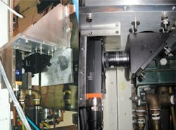
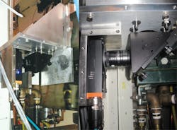
In the past, VBPMs have employed USB 2 and USB 3 cameras from Point Grey (Richmond, BC, Canada; ww.ptgrey.com) connected to video servers located behind a shielding wall via a USB connection. The servers processed the images captured by the cameras and sent images and data via a local area network to the operations facility at CHESS. Recently, however, one of the earlier cameras at the F3 bend-magnet beam line at CHESS has been replaced with a single Currera-R smart camera from XIMEA (Münster, Germany;www.ximea.com) that runs a Windows Embedded Standard 2009 operating system (Figures 1a and b).
Now, image capture and processing is performed by the processor in the camera, eliminating the need for a separate video server computer. In addition, the length limitation of the USB connection between the camera and the server has been overcome, enabling the Currera-R smart camera to be directly connected to the CHESS local area network (LAN) with practically no constraints on distance.
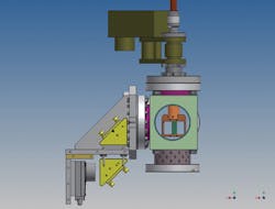
A schematic of the VBPM installed at the F3 CHESS beam line as it appears looking in the downstream direction from the beam is shown in Figure 2. This specific VBPM can be used to monitor the characteristics of a beam using either a thin diamond plate placed on an actuator arm perpendicular to the path of the beam, or by capturing the helium luminescence when the diamond plate is removed. The shielded XIMEA camera is outside the beam pipe on a solid stage and captures images of the beam profile through two 45o mirrors mounted in a periscope arrangement. The mirrors displace the camera from the axis of the beam to further protect the cameras and the camera optics from the X-ray radiation emanating from the system.
Making measurements
To obtain measurements of the beam position in the sub-micron realm, the camera captures and averages a number of image frames. Averaged frame data is then processed to provide details on the beam position, profile, integrated intensity and the full width of the beam at its half maximum (FWHM) size. All the parameters are calculated from the distribution of the luminescence intensity in the cross-sectional footprint image of the beam by custom software developed using Microsoft Visual Studio.
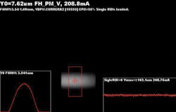
Prior to image capture and analysis, a specific region of interest (ROI) is identified in the cross-sectional image of the X-ray beam (shown as a large red square in Figure 3). Within that ROI, the software finds the center of brightness of the image by calculating the centroid of the intensity of the beam, from which the beam position can be derived. The analysis program calculates the position of the beam in pixels which are then converted to microns. The precision at which the beam can be measured using such a technique has been proven to be well below the sub-micron level.
To determine the FWHM size of the beam, the software integrates the intensities of the pixels along a vertical line from the top to the bottom of the cross sectional image. The result is a semi-Gaussian profile, from whose shape the FWHM value can be derived. This number is then used to compare the difference between images of the beam profile obtained under different conditions.
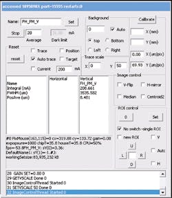
To enable an operator to control the parameters of the smart camera over a Remote Desktop interface, a series of software routines were created in Microsoft's Visual Studio (Figure 4) that can be accessed through Windows based dialog boxes. The software enables an operator to define the ROI in the image, to start and stop the acquisition of images from the camera, and to set the number of frames to be integrated prior to calculating the signal parameters in addition to a number of other image acquisition and analysis parameters.
The software also ensures that the parameters obtained from the analysis of the averaged images are accurate. For instance, to compensate for any spurious light in the background of the images, which could impact the accuracy of the beam position measurement, the software enables fixed levels of background light to be subtracted from the ROI. If that is insufficient to completely eliminate the background, the software also calculates the centroid of the squares of the intensity of the pixels in the image, rather than the intensities. This capability enhances both the low and high intensities of the pixels in the cross-sectional image of the beam, reducing the background noise further.
Due to the high energy X-ray environment in which the VBPM operates, noise in the image can be caused by spurious radiation impacting the pixels of the camera's CCD imager which can adversely affect the calculation of the centroid of the beam. To compensate for these so-called "zingers," a user can also apply a median correction filter to the image that eliminates extreme values of low and high pixels in the frame replacing them with the medium intensity of the pixel array around them. The dark limit of the system can also be modified so that when the beam is at a low intensity or turned off, no images will be acquired by the camera.
Remote viewing
The key intensity, cross sectional and intensity parameters associated with the beam can be viewed using a Remote Desktop connection to both the USB and XIMEA cameras in the VBPM over a local area network. In addition, a "lightweight" data acquisition program running on the camera also saves a JPEG image of the beam and the calculated parameters at a rate of one per second. The JPEG images from all the VBPMs at the CHESS facility are then saved to the CHESS operations center where they can be displayed by an image viewer program. Associated with each of the JPEG images is a stripped down version of the camera control dialog box which enables an operator to modify the key functions of the camera and the image acquisition parameters without the use of a remote desktop connection.
The VBPM can also be used as a diagnostic tool. Misalignment of any beam line components in the beam line upstream from the VBPM can change the beam profile captured by the camera, making the VBPM useful for the initial alignment of upstream beam line components. For instance, if any upstream components are in the path of the beam, the shape of the profile acquired by the VBPM will be asymmetric, resulting in a change in the FWHM calculated by the software. This can then be used to determine if the beam has been inadvertently shadowed by components, which can then be moved.
In addition, the beam position, FWHM and intensity data acquired by the video beam position monitor is acquired over a LAN and used in a closed loop feedback system to control the electron trajectory in the CESR to correct for any deviation of the beam. As a result of implementing such a beam position correction system, the start-up time after regular weekly maintenance can be significantly shortened by introducing frequent beam position corrections. Initial alignments after weekly maintenance periods are then faster, increasing the beam time available for setup, staff development and users alike.
Dr. Peter Revesz,Senior Research Associate, Cornell University, Ithaca, NY
Companies mentioned:
Cornell University
Ithaca, NY, USA
www.cornell.edu
Microsoft
Redmond, WA, USA
www.microsoft.com
Point Grey
Richmond, BC, Canada
www.ptgrey.com
Ximea
Münster, Germany
www.ximea.com
