Velogicfit LTD Develops Machine Vision Assisted Bike Fitting Tool
Velogicfit LTD (Cambridge, New Zealand), a company that specializes in precision cycling analysis and fitting, has developed a machine vision assisted method, Velogic Studio, to assist bicycle outfitters in fitting riders with bikes.
Historically, bike fitting was done with simple static measurement devices, or with nothing more than the practiced eye of an experienced cycle analyst, also known as a bike fitter, says Darren Bruning, chief technology officer and co-owner of Velogicfit. Indeed, the company, which originally started as an online bicycle finder database, got into the technology of bike fitting in 2015, when Bruning, who is both avid cyclist and software engineer of some 25 years’ experience, and his team developed a vision assisted fitting solution.
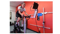
Velogicfit’s solution uses 3D cameras, a computer, and in-house developed software. The goal of the system is to help bike fitters make better recommendations by providing real time data about how their client’s body is moving as he or she rides. The bike fitter can then use that data to decide whether the existing bike needs adjusting, such as a change to the position of the saddle or the handlebars. Once that change is implemented, the fitter can then use the system to check that the intervention performed was a positive improvement.
Ultimately, says Bruning, the goal of the bike fitter is to find the optimal position of the rider’s body in relation to the bike, whether that optimal position emphasizes performance, comfort, or some combination thereof. By using Velogicfit’s tools, a bike fitter can not only better achieve those goals but can help a client understand why a new approach or intervention is more effective.
“This understanding helps the client stick with the changes, which can be initially uncomfortable for a few days while the body adjusts,” Bruning says.
See related content: Boulder Imaging Develops System to Protect Endangered Birds
Components of the Machine Vision Fitting System
Bruning says the system consists of the following:
- Two Orbbec (Troy, MI, USA) Femto Mega ToF cameras, one set up on each side of the rider.
- One Orbbec Femto Mega ToF camera set up in front of the rider.
- One PoE gigabit network switch. All cameras and the PC are connected to the network switch.
- One Orbbec sync hub, which distributes a sync signal to prevent the cameras from interfering with each other.
- In-house developed software. There are three main deployments used. The Windows-based Velogicfit Studios software is installed on the PC. The on-camera software is written in the C# programming language using the ASP.NET Web API framework, an open-source platform used to build HTTP services that can be accessed by any client. Finally, the web software, which is written in C# with the Blazor framework, an open-source front-end web framework based on HTML, CSS, and C# programming languages; this handles the bike database and related web-based tools
“We don't supply computers; we have a set of minimum specs needed to support the system, and our customers provide their own computer meeting those specs,” Bruning says. “The software is completely custom; it uses third-party components for some image processing tasks and a range of other low-level functions, but all algorithms and software development were completed in-house.”
The system also utilizes a hand-held hardware item called a measuring wand, which the bike fitter holds at key locations on a bike frame. The cameras, loaded with imaging software, capture images of the tip of the wand and transmit that data to the Velogic Studio software, which then accurately determines the wand’s position in 3D space. Then, using those 3D locations, the system can generate a set of bike measurements that a rider or fitter can use to either adjust the bike being analyzed or find another bike that matches those measurements.
“You could also consider the cloud to be another component of the system,” Bruning says. “When the fit is complete and the fitter measures the bike position, they can search for real-life bikes from our online database and see which models and sizes could be suitable.”
See related content: 3D Avatar Acccurately Recreates Movements of Athletes
How the Vision System Works
After obtaining basic details from both rider and from a physical assessment of the rider’s bike, the fitter applies eight markers to key joints on each side of the rider's body. The rider then mounts the bike, which is set up on a stationary platform, and starts pedaling.
The cameras are connected to the computer through the gigabit network switch via Ethernet cables. Each camera produces three streams of data at 30 fps. These include:
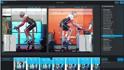
- RGB, used to overlay a "skeleton" on top of the rider. The fitter uses this for qualitative visual cues, such as the rider's head and shoulder position.
- Depth data, used to find points in 3D space for each of the joints in each frame and process that data into the metrics that tell the fitter how the rider's body is moving.
- Infrared data, used to find the joint markers. The fitter can map the infrared data stream into the depth stream for analysis, as well as onto the color stream for display.
The system measures a variety of factors, many of which relate to ensuring that the rider is stable on the bike and minimizing any unnecessary movements, Bruning says. For example, the system will look at joint movement, such as how far the rider’s hip joint moves, how the knees track through the pedal stroke, or whether the toe dips at the bottom of the stroke (which could indicate that the bike saddle is too high).
“We aim to deliver every single data point a cycling analyst needs while synching the 3D data with video,” Bruning says. “The combination of the 3D Kinematics (body angles), the athletes' joint positions (XYZ plane joint movements), the athletes’ power (Ant+) and all the video postural queues, is unique in the world of cycling analysis. With the software installed on the cameras, the system can obtain full 30 fps data from all three cameras on a single gigabit network switch. This makes for a very simple setup and a simple network topology.”
While the software always provides live data based on a moving time window, the bike fitter can also capture separate 15-second snapshots of this motion, Bruning says. One of these snapshots consists of raw video, the metrics that the software has computed, and a "stroke analysis" video, which shows a virtual high-speed capture of a single pedal stroke. The fitter can take as many captures as needed for the fit session and can review any of the snapshots and compare any two side-by-side. At the end of the fit, the computer generates a report that compares the initial and final position of the rider’s pedal stroke.
The system is currently being utilized by bike shops and fitters in over 30 different countries around the world, servicing riders of all skill levels, including a number of elite Olympic, Paralympic and Tour de France riders.
Overcoming 3D Vision Challenges
Bruning said the team did have to overcome a couple of key challenges as they developed the system. For one, they had to solve the issue of body tracking (rider pose) inaccuracies. They initially tried using colored joint markers. However, real world lighting conditions made reliable color detection difficult, so they switched to retro-reflective markers, which are easy to detect using the infrared channel on the cameras. But this led to another issue.
“Basically the ToF sensor is being oversaturated with reflected laser light, but that same oversaturation means that we don't get depth for those pixels,” Bruning says. “We came up with a custom algorithm to interpolate from the edges of the reflective marker to find the midpoint in 3D space.”
Working with three streams of data (color, depth, infrared) at 30 fps was challenging on the computers of mid 2010s, Bruning notes. “Consumer CPUs had two or four cores, so we had to be careful about the image processing algorithms we used and make use of parallel processing pipelines.”
Another issue was accurately determining specific points in 3D space in order to measure a bicycle frame and produce a report of the target position. To do this, they developed a physical “wand” that is detectable in the color stream, based on a series of triangles printed onto a flat face. They found the corresponding points in depth space and extrapolated to find the tip of the wand. But this led to another issue.
“We found that real-world lighting made detection in color space problematic, and this approach was also sensitive to the camera's built-in intrinsic calibration between the color and depth cameras,” Bruning says.
They solved this by developing a second-generation wand that works entirely from the depth space and is detectable through a retro-reflective border. The second-generation wand is more accurate and can work even in complete darkness, Bruning says.
See related content: 3D Sensing Provides Versatility and Precision for Industry
About the Author
Jim Tatum
Senior Editor
VSD Senior Editor Jim Tatum has more than 25 years experience in print and digital journalism, covering business/industry/economic development issues, regional and local government/regulatory issues, and more. In 2019, he transitioned from newspapers to business media full time, joining VSD in 2023.


