Lightfield camera tackles high-speed flow measurements
At Auburn University (Auburn, AL, USA), Brian Thurow, PhD, an associate professor in the department of aerospace engineering, is developing and applying the next generation of nonintrusive laser diagnostics for 2-D and 3-D flow measurements. With the support of the Army Research Office, as part of this research Thurow has developed a pulse-burst laser system that is capable of repetition rates greater than 1 MHz.
To perform 3-D flow visualization, light from this laser is first passed through a cylindrical lens to form the laser beam into a thin sheet. After scanning this light sheet through the flow using a galvanometric scanning mirror, a high-speed camera is then used to take multiple images of the flow.
At Auburn University, Thurow has used this laser in conjunction with an HPV-2 high-speed camera
from Shimadzu (Kyoto, Japan) to capture one hundred 312 × 260-pixel images in 100 μs, forming a 3-D volume with 312 × 260 × 100-voxel resolution.
“This technology is especially important in applications such as jet engine design,” says Thurow, “to analyze how exhaust flows generate intense acoustic noise and high-pressure loads on the aircraft. By
minimizing such effects, vibration or possible damage to the aircraft and surrounding personnel can then be minimized.”
Thurow realized that while a camera that achieves 1 million frames/s, like the HPV-2, could accomplish
the task of capturing the images, similar results could be obtained using a lightfield or plenoptic camera.
Data from single images taken with such cameras can be processed to generate a number of refocused images at different focal distances with a single exposure.
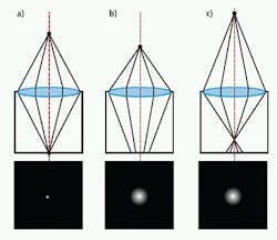
Thurow explains, “In a conventional camera, the angular content of light rays entering the camera is integrated at the sensor plane such that only a 2-D image is captured. Because of this, any depth information is ambiguous—one cannot tell whether the point being imaged is further or nearer to the image plane [see Fig. 1]. This leads to familiar imaging phenomena such as depth of field and out-of-focus blurring.”
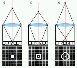
In a plenoptic camera, an array of microlenses is used to sample the angular information of light rays. When the object is in focus, light rays focus to a point, illuminating all the pixels behind a microlens. When the object is out of focus, a blurred spot is formed on the microlens array, but depending on the incident angle of the light, different pixels will be illuminated (see Fig. 2). In this way, the camera is capable of capturing depth and angular information.
With support from the Air Force Office of Scientific Research, Thurow recently designed a camera employing this technology, choosing the Bobcat ICL-B48-20 16-Mpixel camera from Imperx (Boca Raton, FL, USA) supplied by Saber1 Technologies (North Chelmsford, MA, USA). With a 4872 × 3248-pixel CCD interline imager from Kodak (Rochester, NY, USA), the Bobcat camera produces two image pairs at 1.5 frames/s, a feature especially important in particle image velocimetry (PIV), where two images must be taken in rapid succession.
“As important,” says Nathan Cohen, vice president of marketing and sales with Saber1 Technologies, “it was necessary to employ a CCD imager with no on-chip microlenses since a microlens array needed to be mounted separately to the CCD within the Bobcat camera.”
A 287 × 190 microlens array based on a template designed by a research group led by Marc Levoy, PhD, at Stanford University (Stanford, CA, USA) was mounted on the CCD of the camera by Thurow, employing custom components designed by Light Capture Inc. (Riviera Beach, FL, USA). When integrated, this microlens array effectively changes the spatial resolution of the Bobcat camera to 287 × 190 because these are the dimensions of the microlens array. To transfer images from the Camera Link camera, an Imperx Framelink ExpressCard was used to interface the camera to a host PC.
Before any image reconstruction could occur, it was necessary to calibrate the center of each microlens with respect to the Kodak image sensor. This was accomplished using a software routine developed by Auburn University students Kyle Lynch and Tim Fahringer in MATLAB from The Mathworks (Natick, MA, USA).
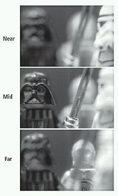
After calibration, a ray-tracing algorithm, also written in MATLAB, was used to produce “virtual images” of images at different focal distances and perspectives (see Fig. 3). In the future, Thurow is looking to deploy the camera to generate 3-D measurements of turbulent fluid flow, and to expand the use of the camera for novel measurements and applications, such as those that may require hyperspectral imaging and depth estimation in a single exposure.
-- By Andy Wilson, Editor-in-Chief, Vision Systems Design


