AEROSPACE: Robots and vision refuel jet aircraft
To speed the turnaround of fighter aircraft involves “hot-pit refueling,” in which the aircraft is refueled while one or more of the engines are running. This is a dull, dirty, and dangerous procedure that can be automated with vision-guided robots. At NIWeek in August 2010 (Austin, TX, USA), Cory Dixon, program manager with Stratom (Boulder, CO, USA; www.stratom.com), showed a robotic-based system developed for this task.
Stratom has developed an automated aircraft refueling robot that uses a programmable automation controller coupled to a laser rangefinder and CCD camera.
Known as the Automated Ground Refueling (AAGR) robot, the system was commissioned by the US Air Force Research Laboratories (AFRL; WPAFB, OH, USA; www.wpafb.af.mil/AFRL/) and has been shown to automate several tasks previously performed by human operators.
“In hot-pit refueling,” says Dixon, “a number of complex tasks including placing of aircraft restraint chocks, aircraft temperature monitoring, and tire inspection must be performed before refueling begins.” After refueling, fuel levels and emergency conditions must be monitored.
Rather than tackle all these tasks as well as aircraft refueling, Dixon and his colleagues focused their efforts on identifying and opening an aircraft’s fuel panel latch, fuel cap handling, insertion of the fuel nozzle, and fuel flow monitoring.
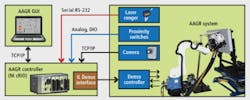
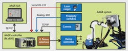
The AAGR system uses a six-axis robot from Denso (Long Beach, CA, USA; www.densorobotics.com) that is mounted on a 30-ft rotary gantry along which the fuel hose is run (see figure). The rotary position of the gantry is determined using a rotary encoder whose value is digitized using a CompactRIO (cRIO) programmable automation controller (PAC) from National Instruments (NI; Austin, TX, USA; www.ni.com).
Once the robot is within working distance of the fuel panel, the robot’s base platform is raised and the approximate orientation of the panel is determined using a laser rangefinder from Keystone Automation (Lake Elmo, MN, USA; www.keystoneautomation.com) that is interfaced to the cRIO system over an RS-232 interface. After the panel is localized, an NI 1764 smart camera is used to capture multiple images of the scene.
“LabVIEW camera calibration code assumes that such cameras are fixed and requires processing of entire images,” says Dixon. So Stratom employed vision-calibration algorithms from The MathWorks’ (Natick, MA, USA; www.mathworks.com) MatLab Camera Calibration Toolbox built by Jean-Yves Bouguet at the California Institute of Technology (Pasadena, CA, USA; www.caltech.edu).
Using these calibrated images and data from the rangefinder, distorted image coordinates are converted to camera frame coordinates and translated and rotated to present real-world coordinates to the Denso robot controller. To determine the corners of the fuel panel, the latch-to-corner angle is computed. While template matching is used to determine the angle of the latch, feature detection determines the location and rotation of the latch’s hexagonal head bolts.
After this process is complete, the robot picks a hex key to systematically unlock each of the bolts in the latch panel. After unlocking, the imaging system is used to locate the SPIR fuel adapter nozzle under the panel. The robot then selects a custom-built fuel adapter tool that is placed over this adapter to refuel the aircraft. After refueling, the process is reversed to seal the panel. This lowers the risk to maintenance personnel, allowing them to remain at a distance from hot-pit refueling. To see a demonstration of the AAGR in action, go to www.stratom.com/Videos.html.
More Vision Systems Issue Articles
Vision Systems Articles Archives

