Sophisticated software analyzes IR data
Infrared camera vendors are adding value by offering image-processing software that rapidly acquires, calibrates, processes, and analyzes IR images.
By Andrew Wilson, Editor
In many machine-vision applications, the properties of the infrared (IR) segment of the electromagnetic spectrum are increasingly being exploited. Ranging from approximately 0.7 to 14 µm, the IR part of the spectrum is generally divided into a 0.7-2.5-µm short-wavelength (SWIR), 3-5-µm medium-wavelength (MWIR), and 8-14-µm long-wavelength (LWIR) region. Both across and within IR spectrums, several different detector materials are used to build focal-plane-array cameras.
For each part of the spectrum, IR cameras meet the requirements of system integrators tasked with inspecting products with specific spectral characteristics (see Vision Systems Design, October 2004, p. 73). At specific wavelengths, for example, IR cameras can image liquid levels in opaque plastic containers, inspect the surface of plastic film using web-inspection techniques, and detect nonhazardous gases such as carbon dioxide.
Unlike their visible counterparts, however, IR cameras remain relatively expensive. This is due to a number of factors that include the exotic detector materials used, the readout integrated circuits that are flip-chip bonded onto the sensor, the market demand, and the cost of the lenses associated with these sensor types (see Vision Systems Design, May 2005, p. 67).
THERMAL IMAGES
One major misconception is that IR cameras are only used to detect the temperature of specific objects within a scene. This misconception has been reinforced by news agencies that commonly show “thermal images” of suspects in darkness leaving crime scenes on foot.
Certainly, IR cameras can be used for this purpose. However, quantum-based devices such as photodiodes that convert incident IR radiation into an electronic signal and thermal detectors such as microbolometers that convert IR radiation to heat both detect the spectral radiant flux of objects within a scene. This flux does not depend on just the temperature of the object within the scene. It also depends on the emissivity-the ratio of the electromagnetic radiation emitted by an object to the amount emitted by an ideal blackbody at the same temperature.
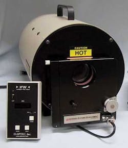
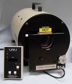
FIGURE 1. Commercially available ideal blackbody radiators such as the IR-574 Series from Infrared Systems Development calibrate IR cameras before they are supplied to the system integrator.
Commercially available ideal blackbody radiators from companies such as Infrared Systems Development are often used to calibrate IR cameras before they are supplied to the system integrator (see Fig. 1). The company’s IR-574 Series blackbody reference sources, for example, are designed to provide IR radiation as an ideal blackbody emitter. The output energy from the 2.25-in. cavity closely follows the theoretical maximum energy curve described by Max Planck’s equation as the spectral intensity of electromagnetic radiation from a blackbody at temperature T
where I(ν) is the amount of energy per unit time per unit surface area per unit solid angle per unit frequency, ν is frequency, T is the temperature of the blackbody, h is Planck’s constant, c is the speed of light, and k is Boltzmann’s constant. This equation is used in both measurement systems and IR camera-software packages to allow designers to calibrate, align, and measure IR devices and generate temperature maps from IR images.
PAPER, CLOTH, FIRE
Since an ideal blackbody absorbs all and reflects none of the radiant energy falling on it, its emissivity closely approximates unity. However, while vendors may assume that emissivity is close to unity in the IR waveband, this is only partially true. Materials such as asbestos, cloth, and paper, for example, may have emissivities of 0.9, 0.95, and 0.95, respectively.
While these materials closely approach emissivities of unity, the same cannot be said for materials such as silicone aluminum paint (0.3), vapor-deposited aluminum (0.02), and polished nickel (0.072). Because emissivity is a measure of how well an object absorbs incident radiation, objects that do not absorb all the incident light (as blackbodies do) will also emit less radiation than an ideal blackbody. Thus, although an object in the IR spectrum may appear to have the same temperature as another (when Plank’s law is calculated assuming an equal emissivity value for all objects in the scene), this may not be true. Unless the system developer can calculate the amount of energy emitted by an ideal blackbody at the same temperature as the object under test, IR measurements may be erroneous.
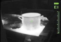
FIGURE 2. Knowledge of the thermal emissivity of objects plays an important role in image analysis. In this thermal image of a steel pot containing boiling water, the surface of the pot must be 212°F (100°C). However, because unoxidized steel has a very low emissivity, the temperature-measurement device indicates a temperature around 110°F (43°C).
In his article “Temperature measurement and thermal imaging cameras” (see Fire Engineering, December 2003, fe.pennnet.com), Jonathan Bastian, former thermal imaging training manager at Bullard, graphically demonstrates the effects of emissivity. The article contains a thermal image of a steel pot containing boiling water (see Fig. 2). Since the boiling point of water is 212°F (100°C), the surface of the pot must be at least that temperature. Yet, because unoxidized steel has a very low emissivity, the temperature measurement device (bar graph to the right) indicates a temperature around 110°F (43°C). A firefighter trusting the temperature measurement might attempt to pick up the pot without a mitt or glove, severely burning his hand.
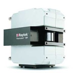
For specialized applications, therefore, where the emissivity of the target is not well known, a blackbody radiator must be incorporated into the IR camera or system. In its MP50 imager, for example, Raytek incorporates a reference blackbody for continuous calibration (see Fig. 3). Targeted at continuous-sheet and web-based processes, the scanner offers a 48-line/s scan speed and is available in versions useful for examining plastics, glass, and metals.
FIGURE 3. In the Raytek MP50 imager, a reference blackbody is used for continuous calibration. Targeted at continuous-sheet and web-based processes, the scanner offers a 48-line/s scan speed and is useful for examining plastics, glass, and metals
Rather than incorporate such a blackbody into its sensor, the Land Instrument Human Body Temperature Monitoring System uses the company’s FTI Mv Thermal Imager with an array of 160 × 120 pixels to capture a thermographic image of a human body (typically the face) at a distance of 2 to 3 m. Data captured are then compared with a blackbody from Isothermal Technology. Permanently positioned in the field of view of the imager, this calibrated temperature reference source provides a reference area in the live image scene. The imager is then adjusted to maintain this reference area at a fixed radiance value.
To overcome such external calibration tasks, many IR detector companies are working on dual-wavelength detectors. At the 2005 SPIE Defense and Security Symposium, QmagiQ showed a prototype of such a “dual-color” IR camera (see Vision Systems Design, June 2005, p. 15). Based on a 320 × 256 dual-color or dual-wavelength detector array, the device can detect IR images in both the MWIR and LWIR bands simultaneously
By taking the ratio of the two signals in both bands, the absolute temperature of every pixel in the image can be computed, provided the emissivity of the target is the same in both spectral bands. Because this is generally true, the absolute temperature can be measured without the need for external calibration, which allows self-calibrating IR cameras to be developed.
While specialized applications may require the use of this calibration technology, many IR systems simply use approximate emissivity values to plot a temperature map of the IR image. This is done by converting the radiance of the signal into a temperature value using Planck’s equation. To perform image acquisition, processing, and display of the data, many IR camera vendors offer standard PC-based software packages that can be used with both their cameras and those from third parties.
SOFTWARE SOLUTIONS
Of the software packages that are available for IR image analysis, many have been developed by the camera companies because each camera system’s specification can vary widely. However, most of these packages are very similar in nature, allowing the system developer to capture, analyze, display, and store images on host computer systems.
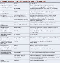
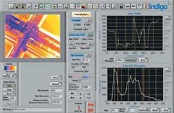
To automate IR measurements in electrical installation maintenance, process control, and machine-vision systems, this software allows system developers to acquire and display image data, calibrate the sensor, and analyze the acquired data. To analyze the data, companies offer tools that can highlight regions of interest, generate line profiles, and histograms (see table). These regions of interest or histogram analyses can then set specific triggers on regions of interest within each of the images and any pass/fail data sent to real-time process control hardware as images are captured. Some packages, such as the IRvista software included with the FLIR Alpha NIR camera, for example, also include software that enables remote camera control, setting of exposure times, and the gain of the camera (see Fig. 4).
FIGURE 4. IRvista software included with the FLIR Alpha NIR camera enables remote camera control and setting of both exposure times and gain.
Recognizing that system integrators may wish to add additional features to their systems, camera and software vendors such as FLIR, Cedip Infrared Systems (distributed by Electrophysics in the USA), Sensors Unlimited, and Winsoft have made their software packages compatible with third-party software such as LabVIEW from National Instruments (NI). In this way, developers familiar with NI’s graphical development environment can acquire, process, and display both still and live IR images while working in the LabVIEW environment.
Cedip’s LabVIEW Toolkit provides these very functions for its line of IR cameras. As well, the toolkit can set sensor integration time, camera frame rate, and triggering conditions in the LabVIEW environment. Like the Cedip product, the Winsoft ThermaVU is a software-development kit (SDK) targeted at developers of IR systems. Using LabVIEW, C++, or Visual Basic, the SDK library supports the FLIR/Indigo Systems camera line.
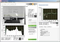
Targeting control of the Sensor Unlimited IR SU320MSW-1.7RT MiniCamera, the company’s latest stand-alone, PC-based executable software options include full control of four preset regions of interest, capture of continuous streaming video at speeds up to 10,000 frames/s, and histogram equalization (see Fig. 5). Images can be saved in a movie format. Operating with NI RS-1422 and -1428 Camera Link frame grabbers, the software also runs under NI LabVIEW Run-Time Engine 6.1.
Before deploying an IR camera, system integrators must consider several important factors. These may include a thorough understanding of the spectral characteristics and the emissivity of the object or material to be inspected. If these can be reliably predicted, then a specific type of IR camera can be specified. However, in a large proportion of applications, including electrical maintenance inspection, the user merely requires an approximate temperature map of the image. In these cases, including some machine-vision applications, a rough approximation of emissivity and a low-cost microbolometer-based camera operating across the 7.5-13-μm spectrum can be used. In other applications, such as target tracking, emissivity may not be known, and it may be necessary to deploy an integrated or external blackbody along with the IR camera to obtain precise radiometric measurements.
Company Info
Bullard
Cynthiana, KY, USA
www.bullard.com
Cedip Infrared Systems
Croissy Beaubourg, France
www.cedip-infrared.com
Compix
Lake Osweo, OR, USA
www.compix.com
Electrophysics
Fairfield, NJ, USA
www.electrophysics.com
FLIR Systems
Billerica, MA, USA
www.flirthermography.com
Infrared Systems Development
Winter Park, FL, USA
www.infraredsystems.com
Ircon
Niles, IL, USA
www.ircon.com
Isothermal Technology
Southport, UK
www.isotech.co.uk
Mikron Infrared
Hancock, MI, USA
www.mikroninfrared.com
National Instruments
Austin, TX, USA
www.ni.com
QmagiQ
Nashua, NH, USA
www.qmagiq.com
Raytek
Santa Cruz, CA, USA
www.raytek.com
Santa Barbara Infrared
Santa Barbara, CA, USA
www.sbir.com
Sensors Unlimited
Princeton, NJ, USA
www.sensorsinc.com
Technische Interaktionen
Bochum, Germany
www.tech-inter.com
ThermoAnalytics
Calumet, MI, USA
www.thermoanalytics.com
Thermotecknix Systems
Cambridge, UK
www.thermotecknix.com
Winsoft
Santa Ana, CA, USA
www.winsoft.com
