Reaching Further
Fiberoptic-based converters extend the camera-to-computer interface
Andrew Wilson, Editor
Camera interface standards such as Camera Link, FireWire, USB, and Gigabit Ethernet (GigE) are now commonplace in the machine-vision industry. Despite their successes, the cable lengths offered by Camera Link, FireWire, USB, and GigE standards often limit their use in applications where a camera must be mounted long distances from the host computer. While GigE-based cameras can be used at longer distances, they are also limited in applications where high EMI is present. To overcome these limitations, many companies now offer fiberoptic-based interfaces that allow cameras that use these interfaces to be deployed at long distances without incurring any signal degradation due to EMI.
According to the Camera Link specification, the length between camera and frame grabber is limited to 10 m. Similarly, the FireWire specification limits this distance to 4.5 m while the USB standard specifies a maximum cable length of 5 m. To extend this distance further, many camera vendors have adopted the GigE standard as an interface, allowing their cameras to be located as far as 100 m from the host computer. Of course, all of these interfaces have their tradeoffs. Camera Link is the fastest interface currently available and cameras based around this standard are found in high-speed machine-vision applications. Where speed is less critical, bus or network-based protocols such as FireWire, USB, and GigE interfaces are often used.
In applications where cable distance and susceptibility to high EMI may limit the deployment of these cameras, systems integrators must use fiberoptic extenders. In operation, these extender pairs convert data signals from Camera Link, USB, FireWire, and GigE standards and transmit it optically over fiber. After this data is received, it is then re-converted into electrical data where it can be stored, processed, and displayed by the host computer. As well as allowing the distance between camera and computer to be extended to hundreds of meters, the resilience of fiber to any EMI or RFI makes the use of camera/extender pair combinations useful in harsh environments such as steel mills and nuclear reactors.
Extending Camera Link
After Camera Link became the de facto high-speed camera interface, a number of companies introduced fiber extenders to increase the distance between such cameras and the host computer. Initially, Camera Link camera developers used 66-MHz transceivers in their designs to implement Base, Medium, and Full camera implementations. These initial designs were then superseded by cameras that used 85-MHz transceivers that increased the data transfer rate of the Camera Link standard (in Full mode, 64 bits) to 680 Mbytes/s.
Not content with this data rate, some camera manufacturers have extend the width of the Full configuration by reassigning some of the framing/enable signals to produce a data path width of up to 80 bits, increasing the bandwidth to 850 Mbytes/s. For example, Full mode cameras, such as Basler’s A504k and Mikrotron’s MC1310 and MC1311, reassign the Spare, Data-valid, and Frame-valid control signals to allow the transport of up to 80 bits of data per pixel clock. Although not specifically endorsed by the Automated Imaging Association (AIA), this “Extended Full specification” is supported by a number of frame grabber companies.
Camera extender manufacturers have responded to the introduction of Base, Medium, Full, and Extended Full Camera Link cameras with numerous products designed to extend Camera Link’s 10-m cable reach (Click here for a complete table listing). Just as Camera Link camera vendors offer their cameras with different clock speeds and Camera Link modes, fiberoptic extender vendors are meeting these needs with a variety of add-on peripherals that range from add-on camera extenders to stand-alone modules, all with different specifications.
In specifying these extenders, systems integrators must evaluate their cameras and the application in which they will be used. While all fiberoptic extenders support camera data signals, the SerTFG and SerTC serial connections, and the three pairs of RS-232 lines of the Camera Link standard, the type of camera configuration, clock speed, and type of fiber interface required must all be taken into consideration.
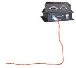
For example, Arvoo’s OpticLink fiber-interface, the CL-Base, supports base (24-bit mode) cameras (see Fig. 1). The 66-MHz interface limits its use to cameras that use 66-MHz transceivers. While a multimode fiber implementation can extend the camera-to-computer distance to 500 m, a singlemode fiber interface can extend this further to 50 km.
null
Going faster
While some extender products operate at the 66-MHz clock rate, some manufacturers have extended their offerings to include the 85-MHz Camera Clock rate found in many high-speed cameras. Logical Solutions, for example, offers a number of different products that allow Base, Dual Base, Medium, and Full configurations to be interfaced to a fiber transceiver. Because of the different number of configurations of the Camera Link standard, each of these products varies in the number of fiber transceivers needed to transmit the data.
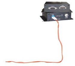
Since many of the fiber transceivers used transmit optical data at speeds of 2.5 Gbits/s, only a single LC duplex fiber connector is required to transmit 24-bit, 66-MHz Base configuration data in Arvoo’s OpticLink CL-Base extender. For higher-performance cameras that use 85-MHz clock rates or up to 80 bits of Extended Full Camera Link mode, however, products such as the CFL-4 Camera Fiber-Link Extender from Logical Solutions require the use of three LC duplex fiber connectors (see Fig. 2).
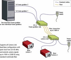
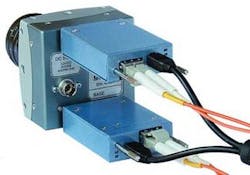
Initially, the first fiberoptic extender modules were offered as stand-alone modules. To extend the Camera Link interface over fiber, systems developers were required to interface their CL cameras with these modules using Camera Link cable connectors. After fiber transmission of the data, these signals were then output from the extender modules using another Camera Link connector and interfaced to the computer’s frame grabber. Recognizing the redundancy in duplicating the Camera Link cable between cameras and frame grabbers and fiberoptic extenders, a number of companies including EDT and Phrontier Technologies offer their extenders as plug-in modules that alleviate the need to use additional Camera Link cable (see Fig. 3).
null
EDT’s RCX C-Link fiberoptic camera adapter, for example, attaches to the back of a Camera Link camera and an LC duplex fiber-optic cable interfaces to the RCX C-Link to allow communication with the company’s PCI DV FOX frame grabber. Alternatively, two RCX C-Link modules can be used as a fiberoptic extension cord with a third-party frame grabber. To accommodate cameras such as the A504k from Basler Vision Components and the MC1310 and MC1311 from Mikrotron, the Spare, Data-valid, and Frame-valid control signals are reassigned to allow the transport of up to 80 bits of data per pixel clock. However, the 72-MHz upper clock limit is determined by the bandwidth available over the fiber.
In specifying their products, many fiberoptic extender manufacturers specify the maximum data configuration and clock speed. For example, Phrontier’s PHAST series can support 10 taps × 8-bit camera data and speeds of up 85 MHz. The available 670-Mbyte/s effective bandwidth of the PHAST system offers sufficient data throughput to cover the maximum output bandwidth of the cameras with extended Full mode capability currently available in the market.
More attractive
What is more attractive, and has been recognized by many companies that offer such products, are the opportunities presented by other camera interfaces such as USB, FireWire, and GigE. Indeed, because USB 2.0, FireWire (1394b), and GigE cameras produce data rates of 480 Mbits/s, 800 Mbits/s, and 1 Gbit/s, respectively, they are much slower than the data rates of Camera Link cameras. Thus, they do not require fiberoptic extenders with multiple fiber pairs.
The FireNEX800 optical repeater from Newnex, for example, uses an IEEE1394 PHY and optical transceiver to extend 1394 signals across an optical fiber cable of up to 500 m. Using a single duplex LC optical connector, the FireNEX800 operates with 1394b at speeds of 800, 400, 200, and 100 Mbits/s, and with 1394a at speeds of 400, 200, and 100 Mbits/s.
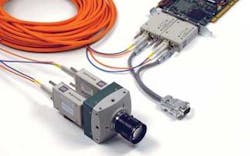
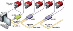
Like Newnex, Opticis also offers fiberoptic extenders for FireWire cameras. Using the company’s S800 Optical FireWire Repeaters offers systems integrators an easy way to configure multiple FireWire-based, optically linked networked cameras. The company’s basic model, M4-200, consists of a pair of two repeaters, having one optical and two electrical ports. Multiple installations of M4-201 repeaters that feature one electrical and two optical ports can then provide a long fiberoptic extension of additional 1394 devices (see Fig. 4).
In a number of FireWire camera configurations, camera power is drawn from the FireWire cable, allowing approximately 7-8 W to be drawn from the six-pin camera connectors. And, since many FireWire cameras do not feature a separate power connector, this must be provided by the fiberoptic transceiver. In Opticis’s M4-200/201 configuration, fiber repeaters are used to deliver both the recovered fiber data and power over an electrical 1394 interface.
Similarly, USB 2.0 specification also specifies a 5-V supply that can initially draw 100 mA and a maximum of 500 mA. Thus, in a fashion similar to FireWire-based systems, USB fiber extenders must also supply power to the camera from their extender modules. To make this transparent, Opticis’s USB converter uses hybrid bundled cables of fiberoptic and copper wires, allowing DC power and data from the host to be supplied to the USB device.
Ethernet too
While many of the well-known fiber-extender manufacturers targeting the machine-vision market offer Camera Link, USB, and FireWire extenders, those involved in producing such products for GigE are firmly based in the telecommunications market. Here, such companies as Advantech, Moxa, and JDSU offer products that, although they can be used to transmit video data, are more suited to extending interoffice copper networks. Indeed, one has to wonder whether there would be any advantage in using such products to extend GigE to distances greater than 100 m.
Possibly, the only need to accomplish such a task would be in cases where a GigE camera was the only camera of choice for a particular application and that the application was deployed in a harsh environment. With more than 2000 different Camera Link, USB, and FireWire cameras now available, however, it appears that there is currently no demand for a GigE fiberoptic camera repeater.
In many fiber extender repeaters, the need to duplicate the electrical Camera Link, USB, and FireWire interface as well as their associated cables, adds cost to a machine-vision system. To reduce this cost, expect future generations of high-speed cameras to adopt onboard fiber interfaces directly. Before this can occur, however, a standard similar to the Camera Link standard needs to be developed so that products from multiple camera vendors will be fiber-compatible.
Company Info
Advantech, Irvine, CA, USA
www.advantech.com
Arvoo, Woerden, The Netherlands
www.arvoo.com
Automated Imaging Association
Ann Arbor, MI, USA
www.machinevisiononline.org
Basler Vision Components
Ahrensburg, Germany
www.baslerweb.com
EDT, Beaverton, OR, USA
www.edt.com
JDSU, Milpitas, CA, USA
www.jdsu.com
Logical Solutions, Milford, CT, USA
www.thinklogical.com
Mikrotron
Unterschleissheim, Germany
www.mikrotron.de
Moxa, Taipei, Taiwan
www.moxa.com
Newnex, Sunnyvale, CA, USA
http://newnex.com
Opticis, Chatham, ON, Canada
www.opticis.com
Phrontier Technologies
San Jose, CA, USA
www.phrontier-tech.com
