New interfaces test camera designers
After integrating a variety of standard interfaces into their products, smart camera vendors are facing a host of new challenges.
By Andrew Wilson, Editor
For smart-camera vendors that have adopted Camera Link, Gigabit Ethernet (GigE), USB, and FireWire interfaces into their products, new challenges are appearing in rapid succession. As these point-to-point and serial interfaces evolve to provide greater functionality and ease of use to the system integrator, smart-camera vendors will be challenged to keep pace while adding increased functionality into their products.
Many interface standards currently face the same challenges. These include integrated power delivery over single interfaces, reduction in size of currently available connectors, accommodation of increased data rates, distance between camera and host, and addition of higher levels of determinism to existing machine-vision systems based on these cameras. Currently, the selection of a specific camera interface-whether Camera Link, GigE, USB, or FireWire-plays a part in determining the specific functionality that can be obtained. But, with the introduction of standards now under development, these distinguishing features are likely to blur.
No power required?
In many of today’s smart cameras, power is supplied to the camera over a separate connector. For the system integrator, this necessitates the use of two cables and increases system cost. In both the USB and FireWire standards, however, power can be supplied to the camera through either the USB or FireWire connector. Although for USB the maximum power that can be supplied over the bus without violating the specification is 2.5 W, USB-based cameras cannot draw more than 100 mA (or 0.25 W) on powerup until the camera and its drivers are loaded by the host PC. For FireWire 1394a and b, this maximum power consumption is 40 V/port at 1.5 A, providing a maximum peripheral power of 60 W.
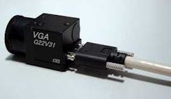
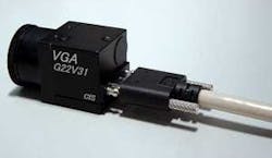
To date, both the point-to-point Camera Link and GigE standards do not allow power to be delivered over the same connector as image data or camera control signals. But many in the industry are pushing to change this. Last year, for example, CIS showed a prototype VGA camera to the Camera Link committee of the Automated Imaging Association (AIA). It incorporated a miniature Camera Link connector that included power-delivery capability (see Fig. 1).
Fumio Nagumo, the director of the technical department at CIS, who was present at Vision Show West (May 2005; San Jose, CA, USA) said that although CIS made no changes to the transmission pin assignment, two of the four camera-control lines have been reassigned to deliver power across the Camera Link connector. According to Toshi Hori, president of Hori Consulting, Micro Technica has already developed a frame grabber to support this proposed revision to the standard. Hori says both camera and frame grabber already have been deployed in a system designed for fruit inspection.
This reassignment of pins, however, has yet to be approved by the AIA (seeVision Systems Design, Dec. 2004, p. 9). Indeed, using this approach would mandate modifying the connector to stop these connectors from being interfaced to current Camera Link connectors, placing increased burden on frame-grabber companies. Because of this, others such as Steve Kinney of JAI Pulnix have suggested use of two inner grounds to transfer 5-V power so that there would be no need to redesign the connector, and the chances of electrical damage would be minimized.
Members of the IEEE also wish to add power to Ethernet-based data-transfer devices. Two years ago, the IEEE published its IEEE 802.3a Power over Ethernet (PoE) standard, which specifies how to deliver power over standard Ethernet cables. This allows up to 48 V of dc power to PoE-compliant devices over eight-wire Cat 5 and Cat 6 cables. Two types of architecture currently exist: mid-span and end-span. Mid-span involves running power over unused wire pairs in a LAN cable. Mid-span products are built into patch panel-like devices that can add PoE to existing LAN infrastructures. In end-span devices, dc power signals are run over the same wire pairs used for data transmission.
“The idea of delivering power over the communication cable is excellent, but there are some problems,” says Petko Dinev, president and CEO of Imperx. “Most CCD megapixel cameras operate from 12 Vdc and consume 5 to 24 W in power (ours are 6 W), so the current requirements for the power cable has to be at least 2 A. Most of the standard cables (GigE or Camera Link) can support only 0.5 A. In addition, the internal (Camera Link or GigE) cable resistance (#28 AWG) is 65 mW/ft, so in long cables (such as GigE) and high current this is a serious problem. One solution is to use a higher voltage 24 Vdc (or 48 Vdc), but this may upset some camera manufacturers. In addition, the computer (or frame grabber) has to provide this voltage, and 24 Vdc (or 48 Vdc) is not readily available (12 Vdc is standard). So while the idea is good, the infrastructure is not in place.”
Increased data rates
In addition to adding power over existing data interfaces, many smart-camera vendors are looking to increase the data throughput of their devices. Here, too, a number of standards, implementations, and roadmaps will pave the future for Camera Link, GigE, USB, or FireWire-based devices. Unfortunately, whether these standards will be implemented remains to be seen.
While USB 1.1 supported both a low speed of 1.5 Mbits/s and full speed of 12 Mbits/s, the USB 2.0 specifies a high-speed transfer mode of 480 Mbits/s. However, because the bus must carry status, control, and error-checking signals, the actual data rate at which a camera can transfer image data over the bus is reduced. This reduction can also be compounded by other cameras and peripherals that may share the bus.
Like USB, the bandwidth of FireWire peripherals has also increased over the last few years. While the first generation of the standard specified a 400-Mbit/s data rate, 1394b technology increases this bandwidth to 800 Mbits/s. Future generations are predicted to reach speeds as fast 3.2 Gbits/s. But the road to increased speed has not been easy. To implement their first generation of 1394a cameras, vendors could use off-the-shelf physical (PHY) and LINK devices in their designs. Unfortunately, due to the lack of support for a general purpose LINK device, many camera vendors, including Point Grey Research and Allied Vision Technologies, have developed their own 1394b LINK layer devices in FPGAs and have introduced related products.
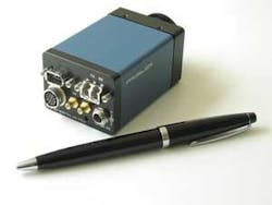
Prosilica was one of the first companies to offer IEEE 1394b cameras when it introduced its CV1280F and CV640F fiberoptic output cameras (see Fig. 2). Although these cameras incorporate a 1394b physical layer, a 1394a LINK layer is used due to the lack of off-the-shelf 1394b LINK layer from Texas Instruments (TI) and other suppliers. Thus, although 1394b-compatible, the cameras run at 1394a speeds.
“There is still no off-the-shelf 1394b LINK layer from TI or any other supplier that is suitable for use in machine-vision cameras. TI’s PCI link is not suitable for cameras at all, and it is easier to implement a 1394b LINK layer in an FPGA than it is to adapt the PCI LINK layer for use in a camera. This is why all camera companies with IEEE 1394b cameras running at 800 Mbits/s have used an FPGA link layer. The PCI OHCI link is only useful for the computer side of the equation, not the device side,” says Marty Furse, Prosilica CEO.
Certainly, the promise of higher data rates is being fulfilled by camera vendors who will no doubt build on the 1394b standard as the 1394c standard nears completion. “The 1394c standard should receive final approval before the end of 2005,” James Snider, executive director of the 1394 Trade Association, said in a recent magazine article. “A way for the 1394 protocol to run on an Ethernet PHY, 1394c is an attempt to jump-start 1394 as a networking technology, where it has had trouble gaining acceptance,” he says.
Some manufacturers of GigE cameras are already claiming 1.2-Gbit/s speeds. But like USB and FireWire, this theoretical maximum data-transfer rate is limited by a number of factors. Although GigE’s signaling rate is theoretically 1.25 Gbits/s, the 8B/10B encoding used to reduce the bit error rate results in a data transmission rate of 1000 Mbits/s. To gain these speeds, the IEEE 802.3 Ethernet and ANSI X3T11 Fibre Channel standards were merged into the GigE standard, allowing users to take advantage of the physical interface technology of Fibre Channel and keep the IEEE 802.3 Ethernet frame format.
However, not all GigE cameras are created equal. While most available cameras use Intel’s 8254XX family to implement the Gigabit PHY/LINK to present a standard GigE interface, it is there that the similarities end. Just as USB and FireWire devices are limited in data reduction transfers by other cameras and peripherals, so too are GigE cameras.
For this reason, the AIA is developing GigE Vision, a standard that will define how to control GigE Vision-compliant cameras, specify stream channels, and provide a mechanism for cameras to send image and other data to a host. As well as defining data types and how images are transmitted over GigE, the standard will also specify how cameras obtain IP addresses and how applications control the devices on a network (seeVision Systems Design, June 2005, p. 43).
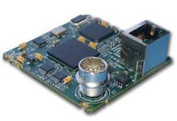
Already, Pleora Technologies, a pioneer in the development of GigE for vision, has launched an OEM board for in-camera GigE connectivity-the iPORT PT1000-VB In-Camera Engine-that can be field-upgraded to comply with the AIA standard, once it’s released (see Fig. 3 on p. 55). Pleora has also announced agreements with Atmel, Basler Vision Components, and Dalsa to collaborate on GigE vision connectivity products. In addition, JAI Pulnix has worked with Pleora to embed GigE interfaces into a series of cameras targeted at machine-vision applications.
Because of the number of interface standards now available, many of those in machine vision are looking for road maps that guarantee future and backward compatibility with existing products. But for the Camera Link standard, it seems, no such road map is forthcoming. Although still the fastest way to transfer data at 680 Mbytes/s (max) from camera to frame grabber, the point-to-point interface has not yet emerged into a “plug and play” interface, such as USB and FireWire. And, despite the speed offered, high-speed camera vendors such as Basler have already challenged the standard in products such as the A504 series of high-speed cameras. Faced with transferring 1280 × 1024 at 500 frames/s to a frame grabber while maintaining Camera Link compatibility, Basler redefined the standard’s data valid to transmit video data.
Very deterministic
When designing machine-vision systems, developers are often faced with ensuring that specific events occur within limited periods of time. Such levels of deterministic behavior are application specific. System integrators involved in building a code reader that must read 200 codes per second face a different task than those involved in developing a system to count cells under a microscope. In both cases, the application to be solved determines the level of determinism required.
For many years, the level of determinism of a machine-vision system has depended on the type of operating system used. In “deterministic” real-time operating systems, I/O, timing, and task-management services allow the systems developer to determine the expected time a specific task will take. In “nondeterministic” operating systems, such as Windows, random service times can result in the vision system missing real-time deadlines. In many medical, agricultural, and automotive applications, this is unacceptable.
Unfortunately for developers, varying degrees of determinism appear throughout the image capture, processing, and analysis process. In choosing a smart camera, system developers must balance the benefits of data-transfer rates and determinism. While Camera Link, USB, and FireWire are all deterministic interfaces, for example, Camera Link is faster than either one of the others.
Camera Link is a simple point-to-point interface that can transfer data at up to 680 Mbytes/s. It is truly deterministic, since data clocked from the camera to a frame grabber over this serial parallel interface will arrive within a specific time period (the clock rate).
USB and FireWire interfaces are also deterministic. Both support isochronous and asynchronous data transfer modes. Because isochronous data transfers require a constant bandwidth within specific intervals, data bandwidth is guaranteed. After data are sent using the FireWire or USB isochronous mechanism, the remaining time is used to accommodate asynchronous data transfers. These use a handshaking scheme and are often used by camera manufacturers to control specific functions of the camera. While FireWire devices implement isochronous mechanisms in hardware, USB uses a host-based software mechanism to perform this task. “Thus,” says Scott Israel, president of 1stVision, “CPU use is higher in USB-based systems than those based on FireWire. Since USB peripherals outputs data only when requested by the host CPU, system latency is often higher.”
Ethernet and GigE are by nature nondeterministic, since they lack any isochronous mechanism. Although the IEEE standards show how to prioritize individual packets it cannot guarantee a specific bandwidth or system latency. To attempt to address these concerns, the AIA’s GigE Vision standard shows how to prioritize individual packets using the GigE Vision Control Protocol (GVCP). This defines how to control GigE cameras and specify stream channels and provides a mechanism for cameras to send image and other data to a host.
Currently, GVCP runs on top of the User Datagram Protocol (UDP) IPv4. UDP delivers efficient transfer performance, but does not guarantee data delivery. To address this, GVCP defines mechanisms to guaranty reliable packet transmission and ensure minimal flow control. To avoid IP fragmentation and ensure data transfer through the LAN, the user’s application should negotiate packet size with the camera. The do-not-fragment bit in the IP header can be used to ensure packets remain intact during transmission across a network. Although the GigE protocol lacks isochronous data transfer capability, this does not mean that, unlike Camera Link, USB, and FireWire, it lacks determinism. In point-to-point camera-to-computer data transfers, this lack of deterministic capability may, to some extent, be mitigated by the 1-Gbit/s data rates that can be achieved.
“For point-to-point connections such as one camera, and one PC connected by a single Cat-5 Ethernet cable over GigE,” says George Chamberlain, president of Pleora, “the lack of a specific isochronous channel has no effect on the deterministic nature of the image delivery. For switched connections over GigE that use multiple cameras in a single network, the variability of the delivery of the image data is less than the transaction interval for 1394a and USB cameras and much less than the scheduling time in non-real-time operating systems such as Linux and Windows,” he says.
More standards anyone?
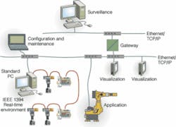
In applications where IEEE 1394 is used for industrial control systems, factory automation, or motion control, proprietary protocols have been used, since no international standard exists. That’s about to change as companies including Basler Vision Components have formed the 1394 Automation Group under the technical leadership of Michael Scholles and others at the Fraunhofer Institute for Photonic Microsystems. The 1394 Automation Protocol (AP) will allow subsystems for factory automation and motion control from different vendors to communicate with each other via IEEE 1394 (see Fig. 4).
In its first incarnation, the IEEE1994AP uses an Application Master and up to 62 slaves. The Application Master is responsible for the transfer of data to the devices and uses a payload of an IEEE 1394 packet called a Master Data Telegram (MDT). While slave devices receive the MDT and extract the data for proper operation, they output they data via Device Data Telegrams (DDT) that transfer data both to the Application Master and to other devices in a peer-to-peer fashion. In this way, the MDTs and DDTs define the software interface of 1394AP to the application software. To ease migration from other bus solutions to 1394AP, without the necessity to rewrite major parts of the application software, communication profiles such as the CANopen Communication Profile will be adapted to 1394AP.
But it’s not just plug-and-play capability, power, smaller connectors, and greater bandwidths that future network-based systems may deliver. Recently, the IEEE introduced the IEEE 1588 standard that specifies a precision clock-synchronization protocol for networked measurement and control systems.
“While not tied to a specific network implementation, IEEE 1588 works by measuring the delays between sections of the network and using in-band signaling to adjust its local oscillator,” Matthew Linder, president of Valde Systems. “Depending on the accuracy of the local oscillator, submicrosecond accuracy can be achieved. This will be very useful in future systems, where devices such as high-speed shutters and strobe lights that comply with the standard could be programmed to occur in synchronization with the camera trigger,” he says.
However, the choice of which smart camera to choose may ultimately be decided by marketing rather than engineering. “There are several reasons for this,” says Prosilica’s Furse. “First, the power of the name ‘Ethernet,’ right or wrong, speaks to ease of use and integration. Second, if properly implemented, GigE offers everything that FireWire does and more. Furthermore, when 10-GigE cameras begin to appear even Camera Link will not have anything to offer.
“The companies that are currently selling GigE cameras are seeding the market for a wave of GigE cameras that will begin to appear in the next 12 months,” says Furse. Although the AIA GigE Vision standard may have shortcomings, its emergence will signal the beginning of the end of the ‘interface wars.’ Properly implemented, GigE offers higher data rates, standardized camera protocols (thereby reducing integration costs), long cables (easily and economically manufactured on site), and standardized computer interfaces. This all favors a strong move toward GigE in the near future,” adds Furse.
Despite the feverish activity now occurring in standards committees worldwide, the choice of which smart camera to choose ultimately will be decided by the added functionality that vendors incorporate into their cameras. Already, many camera vendors are offloading simple functions such as gamma correction and Bayer decoding into their cameras. Some, such as Banner Engineering, Cognex, DVT, Matrix Vision, and Vision Components, have embedded CPUs, DSPs, FPGAs, and memory to achieve higher levels of image-processing and machine-vision capability.
When such processing is performed in the camera, the task of transferring volumes of image data across networks becomes of less concern since the network or simple voltage triggers are used to signal any pass/fail. Ultimately, for the systems integrator, it may be the functions that the smart camera can perform within a specific time period and not the camera interface used.
Company Info
| 1stVision Andover, MA, USA www.1stvision.com | 1394 Trade Association www.1394ta.org |
| Allied Vision Technologies Stadtroda, Germany www.alliedvisiontec.com | Atmel San Jose, CA, USA www.atmel.com |
| Automated Imaging Association Ann Arbor, MI, USA www.machinevisiononline.org | Banner Engineering Minneapolis, MN, USA www.bannerengineering.com |
| Basler Vision Components Ahrensburg, Germany www.basler-vc.com | CIS Tokyo, Japan www.ciscorp.co.jp |
| Cognex Natick, MA, USA www.cognex.com | Dalsa Coreco St.-Laurent, QC, Canada www.imaging.com |
| DVT Duluth, GA, USA www.dvtsensors.com | Fraunhofer Institute for Photonic Microsystems Dresden, Germany www.ipms.fraunhofer.de |
| Hori Consulting Milpitas, CA, USA www.horiconsulting.com | Imperx Boca Raton, FL, USA www.imperx.com |
| JAI Pulnix Sunnyvale, CA, USA www.jaipulnix.com | Matrix Vision Oppenweiler, Germany www.matrix-vision.com |
| Micro Technica Tokyo, Japan www.microtechnica.co.jp | Pleora Technologies Ottawa, ON, Canada www.pleora.com |
| Point Grey Research Vancouver, BC, Canada www.ptgrey.com | Prosilica Burnaby, BC, Canada www.prosilica.com |
| Texas Instruments Dallas, TX, USA www.ti.com | Valde Systems Brookline, NH, USA www.valdesystems.com |
| Vision Components Ettingen, Germany www.vision-components.com |
