CALIBRATION BOOSTS medical image displays
CALIBRATION BOOSTS medical image displays
By Peter Steven
Digital-based picture archiving and communication systems (PACSs) have been around for more than a decade. But network, computing, and display technologies have improved only recently to the point where PACSs are financially and technically viable. In today`s hospitals, with their centralized radiology centers, PACSs are viewed as an enabling technology that will provide increased efficiency and cost savings. But because image quality is only as good as that of the display device, many issues still remain about the suitability of monitors for radiographic diagnosis. While effective standards exist for film, none exist yet for high-resolution displays.
Calibrating display systems
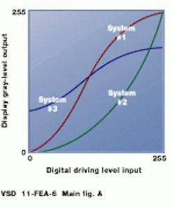
Photosensors used in cameras and monitors do not have a uniform response to light intensity. Digital-to-analog converters (DACs) driving monitors transfer digital values to luminance values. The relationship between input voltage and output luminance is defined as a gamma function; technicians often refer to monitor adjustments as "gamma corrections." The same chest x-ray displayed on the three monitors characterized in the figure (a) would appear quite different.
These nonlinearities reflect normal variations in the phosphors and electronic components of the monitor. Even identical monitors from the same manufacturer will have different gamma functions. Furthermore, monitors wear out over time, and their gamma functions drift. These changes are usually very gradual and nearly impossible to detect with the unaided human eye.
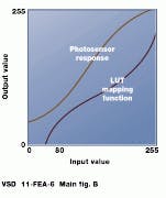
The input-output response of a display system can be modified by a device known as a look-up table (LUT)--a hardware or software function that converts a set of input pixel values to a set of output pixel values. LUTs are commonly used in color systems to set palettes and to make consistent color presentations across a range of scanners, monitors, and printers. In gray-scale systems, LUTs can be used to window and level images. If the properties of a photosensor can be measured in advance, a LUT mapping function can be created to produce the desired output on subsequent images (see figure [b]). Calibration is the process of measuring the response of a device and then adjusting to a desired input/output function.
Medical implications
Radiologists make diagnoses based on small changes or anomalies in image data. They need high-quality images with high spatial and gray-scale resolution and low distortion. In addition, images must be presented consistently across all viewing stations. In radiology departments, doctors often need multiple displays to view images or to examine a series of images. Quad-headed monitor stations are common. These monitors frequently offer very high spatial resolution, often up to 4 or 5 Mpixels. Dr. Joel Grey, a medical physicist in diagnostic radiology at the Mayo Clinic (Rochester, MN), says, "It is essential that two radiologists looking at the same image see the data presented in a consistent way, whether radiologists are in the same or different cities." Without these assurances, radiologists are hesitant to use such systems and will continue to use film-based approaches.
Radiologists using early PACSs often spent minutes adjusting the brightness/ contrast settings of their display devices to "improve" images. This leads to inconsistency. To discourage radiologists from making changes, PACS vendors are encouraging suppliers to place adjustment controls at the back of monitors or in an inaccessible location.
Because this is a serious issue, the American College of Radiology (ACR) has established a working group to develop standards for display calibration. After the adoption of the ACR--NEMA standard, all PACS systems will be adjusted to the same consistent parameters (see "Working group standardizes display calibration," p. 18).
Automating calibration
While the goal of a quality-control program for PACS viewing stations is to ensure optimal display of medical information, quality control must be practical. If an image-integrity program requires 20 minutes to characterize and calibrate a monitor, and if the procedure were performed just twice per month on 120 monitors, then a hospital would need a technician just to perform quality control. Fortunately, new display systems are being introduced that offer a built-in hardware/software option for automatic calibration. With this innovation, the display controller measures the monitor`s output for a series of input values, calculates a correction table, and loads the table into the output LUT. This is performed automatically in about two minutes and requires little user intervention. More important, it makes the calibration task objective rather than subjective, protecting image integrity.
Newer display controllers combine built-in automatic display calibration and 10-bit DACs with a flexible LUT architecture optimized for medical applications. These boards handle image data up to 16 bits deep. Separate LUTs for window/level control and for gamma correction enable a separate LUT correction to be applied to different areas of interest on the display, for example, bone vs. tissue. Hence, an operator can apply different (DICOM standardized) window and level settings to different CT scans viewed simultaneously on the monitor.
With calibration standards blessed by the ACR, physicians will be presented with consistent images across a range of monitors. And, tying these standards to off-the-shelf display controller cards and high-resolution monitors will lead to a greater acceptance of digital imaging systems. When deployed, such systems will increase the efficiency of diagnosis while, at the same time, increasing patient throughput.
Because of the different gamma functions of monitors, images displayed on one system will not necessarily look the same as images displayed on another (top). To correct for this, look-up tables can map display output functions to match the response of the system (bottom).
Resolving the resolution issue
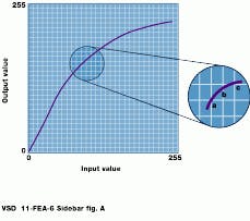
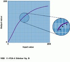
Most imaging systems deal with 8-bit pixels, and look-up tables (LUTs) in many display systems have 8-bit inputs and 8-bit outputs. This means that any nonlinear mapping scheme requires that certain values be repeated. Pixels with unique input values a, b, and c cannot be mapped to three unique output values; one value is repeated, and some of the original information is lost. This is unacceptable in medical imaging. But if a 10-bit digital-to-analog converter (DAC) is used with 8-bit data, pixels a, b, and c can be mapped into unique output values and no information is lost.
Fortunately, 10-bit DACs are now available to drive high-resolution monitors. The 10-bit systems give the full range of grays needed to view high-density tissue and low-density bone in the same image.
Because of this, "banding," or false contouring, in the image does not occur. Experience has shown that losing display data is not unusual with an 8-bit RAMDAC. However, this could be a loss of medically significant information. With 8-bit pixel values and a 10-bit LUT, the higher resolution gives noticeably superior images in many cases.
With 8-bit DACs, pixels with unique input values cannot be mapped to unique luminance levels, and original information is lost (top). By using a 10-bit DAC, the range of output levels is increased, allowing unique output luminance values to be produced (bottom).
Working group standardizes display calibration
Because digital images are displayed as a discrete set of brightness values, the ability of the eye to discriminate between them is important. The range of light intensity levels to which the human visual system (HVS) can adapt is about 1010 from the perception of the dimmest light to the glare limit. Considerable evidence suggests that subjective brightness--the brightness as perceived by the HVS--is a logarithmic function of light intensity.
More remarkable than its wide dynamic range is the ease with which the eye adapts itself to brightness levels. A just noticeable difference (JND) in the intensity of an image is nearly the same percentage change in luminance near the black part of the image as near the white part. Thus, a larger change in luminance is required in the bright part of an image for the human eye to perceive that there has been a change compared to the change needed in the dark region.
This is a fundamental relationship being addressed by the American College of Radiology (ACR)--NEMA Working Group 11--a standards committee established by the ACR to create an objective, quantitative display-function standard and to standardize the procedure for display calibration. Results will specify how to map digital driving level values to luminance (brightness) values. This will result in a mathematically defined input-output response for gray-scale monitors (and film printers) over a range of luminance values.
The ACR--NEMA model is based on perceptual linearization; a monitor is perceptually linear ized when equal increments in digital input produce equally perceived luminance differences throughout the entire range of digital input values. Thus, there will be the same number of JNDs in dark and light regions of an image. When adopted, the efforts of Working Group 11 will enable a consistent response curve for diagnostic image-presentation systems.


