Low-cost components make portable fundus cameras a reality
Using off-the-shelf cameras, processors and displays with a custom NIR and white light LED allows portable fundus cameras to be developed at low-cost.
Andrew Wilson, European Editor
To monitor eye diseases such as increased pressure in the eye (glaucoma) and document any potential of damage to the retina from diabetes (diabetic retinopathy) such as retinal neovascularization, hemorrhage, and macular edema, it is necessary to image the retina. This is performed by ophthalmologists using fundus cameras - specialized optical instruments with attached cameras to view between 30-50° of the retinal area.
To perform fundus imaging, the patient’s pupil is usually dilated using a mydriatic agent that dilates the pupil since, as a reflex, the pupil will constrict when subjected to the bright light used by the fundus camera. One effect of such mydriatic agents is to cause blurred vision and sensitivity to light for hours after the exam depending on the mydriatic agent used.
To avoid this, a class of optical devices known as non-mydratic fundus cameras can perform retinal image analysis without dilating agents. This eliminates the discomfort associated with the dilating drops and the 30-minute wait required for the pupil to dilate before the fundus examination can be performed.
No dilation
“In such non-mydriatic fundus cameras,” says Dr. Shizuo Mukai of the Massachussetts Eye and Ear Infirmary at Harvard Medical School (Boston, MA, USA; https://hms.harvard.edu), “the eye is subjected to near-infrared (NIR) light which does not cause the pupil to constrict. Reflected NIR images are then captured and displayed and, when the image is properly focused, a white flash of light illuminates the retina and the reflected color image is captured by the camera.”
Recent advancements in mobile technology, cameras, displays and illumination systems have now made the development of portable non-mydratic fundus cameras a reality. To demonstrate the feasibility of such a camera, Dr. Shizuo Mukai and his colleague, Dr. Bailey Shen of the Department of Ophthalmology at the Illinois Eye and Ear Infirmary at the University of Illinois at Chicago (Chicago, IL, USA; www.uic.edu), have developed a prototype of such a camera using mainly off-the-shelf low-cost components (http://bit.ly/VSD-NONMFC).
To perform image capture, processing and display, the camera uses a Raspberry Pi 2 Model B from the Raspberry Pi Foundation (Cambridge, UK; www.raspberrypi.org), an embedded processor based on a 900MHz quad-core Cortex-A7 CPU from ARM (Cambridge, UK; www.arm.com) that features a micro SD card, four USB ports, 40 general purpose I/O (GPIO) pins, 1GBytes RAM, a CSI camera interface and an HDMI display interface.
Spectral sensitivity
To capture images, the board is interfaced to a NoIR camera board, also from the Raspberry Pi Foundation. Based on the 2592 x 1944 CMOS OV5647 sensor from OmniVision (Santa Clara, CA, USA; www.ovt.com), this 25 × 25 × 9 mm camera board has spectral sensitivity in both the visible and NIR and is interfaced to the embedded processor using a 15-pin mobile industry processor interface (MIPI) with a ribbon cable (Figure 1).
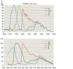
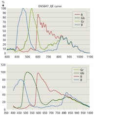
Figure 2: While the spectral sensitivity of the OV5647 sensor falls off in the NIR spectrum from 780-2500nm (top), the sensitivity is still good enough to capture NIR images. Version 2 of the camera board will employ the IMX219, a 3280 x 2464 CMOS image sensor (bottom). As can be seen, the spectral response of both sensors are very similar.
While the spectral sensitivity of the OV5647 sensor falls off in the NIR spectrum from 780-2500nm, the sensitivity on the NIR region is still good enough (Figure 2) to obtain an image that can be used by an operator to focus the camera. However, since the OV5647 is now an end-of-life (EOL) product, the Raspberry Pi Foundation has replaced it in the company’s Version 2 Pi NoIR camera module v2 (Pi NoIR) with the IMX219, a 3280 x 2464 CMOS image sensor from Sony Semiconductor Solutions (Tokyo, Japan; www.sony-semicon.co.jp).
This sensor board, like the Raspberry Pi Foundation’s v1 of the board, does not employ an IR filter and has a spectral response peak sensitivity in the NIR domain of approximately around 810nm (Figure 2). As can be seen, both the spectral response of the EOL OV5647 and the IMX219 are similar.
Shining lights
“Because the standard lens of the Version 1 Pi NoIR camera board is focused at infinity from the factory,” says Dr. Mukai, “it was necessary to change the focus of the lens to approximately 8cm by unscrewing the lens counter-clockwise.”
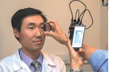
In operation, a handheld 20 diopter condensing lens from Sensor Medical Technologies (Maple Valley, WA, USA; http://sensormedtech.com) was used to image the retina onto the camera board (Figure 3). “Illumination of the retina proved critical in the design of the camera,” says Dr. Mukai. “The retina must first be imaged with NIR light to properly align the patient’s retina and pupil and then white light used to render a color image.” Thus, both the NIR and color images of the retina must be illuminated using the same lighting configuration.
Figure 3: Dr. Bailey Shen of the Department of Ophthalmology at the Illinois Eye and Ear Infirmary at the University of Illinois at Chicago demonstrates how the portable fundus camera is used.
To accomplish this, an illumination system consisting of a prototype dual NIR/visible LED manufactured by Ushio Epitex (Kyoto, Japan; www.epitex.com) and distributed by Marubeni (Tokyo, Japan; www.marubeni.com) was employed. As well as providing stable coaxial brightfield illumination, the coaxial configuration of the 3 x 3.5mm illumination system results in direct reflection from the surface of the retina to the camera.
Configured par-axially to the NoIR’s camera lens, the LED is connected to the Raspberry Pi’s processor board and powered and triggered using cables connected to the GPIO pins on the board. In operation, the camera is first powered using a 10400mAh Lithium battery which is connected to a micro-USB cable. This initiates the NIR illumination system and the camera’s viewfinder.
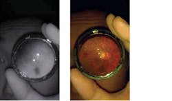
After the NIR image is captured (Figure 4), it is displayed on a Model KD50G21-40NT-A1 5-in LCD touch screen from On Tat Industrial Company (Hong Kong) and distributed by Adafruit (New York, NY, USA; www.adafruit.com). This interfaces to the Raspberry Pi 2 processor board via both a USB cable and an HDMI cable and is powered from the lithium battery.
When an acceptable image is displayed, triggering a push-button switch turns off the NIR illumination, flashes the co-axial white LED and captures a color image of the fundus (Figure 4). The switch is interfaced to the Raspberry Pi’s processor board using the GPIO pins. “This image can then be accessed from the Raspberry Pi’s micro SD card, transferred over Ethernet or transmitted wirelessly to a host computer,” says Dr. Mukai.
Programming the Pi
To program the fundus camera, Rasbian, the Raspberry Pi’s operating system (OS) was loaded from an 8GByte micro-SD card using the Raspberry Pi Foundation’s New Out Of the Box Software (NOOBS) operating system installer. This was loaded by typing commands to the Raspberry Pi using the open-source Florence virtual keyboard program available from SourceForge (https://sourceforge.net) displayed on the LCD touchscreen.
Figure 4: In operation, the camera is first powered to initiate the NIR illumination system and the camera’s viewfinder. After the NIR image is captured (left), it is displayed on the system’s 5-in LCD touch screen. When an acceptable image is displayed, a push-button switch is used to flash a coaxial white LED and capture a color image of the fundus (right).
As an extensible, scalable virtual keyboard for X11, a windowing system used for bitmapped displays, the Florence keyboard program can be downloaded at http://bit.ly/VSD-FLO. To control the fundus camera, a program written in Python by David Jones of the Raspberry Pi Foundation was used. This can be accessed from the Foundation’s Website at http://bit.ly/VSD-PICAM.
To simulate the operation of the camera in use, a 20-diopter condensing lens was used to focus light on the sensor head. “The risk to biological tissues from light damage (phototoxicity) depends on the energy delivered to those tissues. For example, tissues are treated with a laser, the energy settings are specified in milliWatts (mW). With retinal imaging devices, keeping the energy delivered to the retina as low as possible minimizes the chance of phototoxicity.”
The intensity of both the NIR and white light produced by LED used in the fundus camera was measured using a PM100 optical power meter fitted with an S120B sensor head from Thorlabs (Newton, NJ, USA; www.thorlabs.com).
When the portable fundus camera was exposed to NIR light from the LED, between 50-90μW of light energy was recorded at 850nm. When exposed to white light, between 150-170μW of light energy was measured at 570nm. “In comparison,” says, Dr. Mukai, “an opthalmoscope in common use such as the Vantage Plus from Keeler Opthalmic Instruments (Broomall, PA, USA; www.keelerusa.com) set to half and full light intensity produced approximately 1.5mW and 3mW of light energy at 570nm, respectively.
In “Fundus Photography in the 21st Century—A Review of Recent Technological Advances and Their Implications for Worldwide Healthcare,” Nishtha Panwar of the School of Electrical and Electronic Engineering, Nanyang Technological University (Singapore; www.ntu.edu.sg) points out that today’s tele-ophthalmology systems are large and often based in clinics.
“In future,” Panwar says, “retinal cameras must address this need by featuring low-cost, portable designs capable of transmitting images over the Web.” (http://bit.ly/VSD-FUNPH). Certainly, developments by Dr. Shizuo Mukai at Harvard Medical School will provide an incentive to develop such products to address such requirements.
Companies mentioned
Adafruit
New York, NY, USA
www.adafruit.com
ARM
Cambridge, UK
www.arm.com
Harvard Medical School
Boston, MA, USA
https://hms.harvard.edu
Keeler Opthalmic Instruments
Broomall, PA, USA
www.keelerusa.com
Marubeni
Tokyo, Japan
www.marubeni.com
Massachusetts Eye and Ear Infirmary
Boston, MA, USA
www.masseyeandear.org
Nanyang Technological University
Singapore
www.ntu.edu.sg
OmniVision
Santa Clara, CA, USA
www.ovt.com
On Tat Industrial Company
Hong Kong
Raspberry Pi Foundation
Cambridge, UK
www.raspberrypi.org
Sensor Medical Technologies
Maple Valley, WA, USA
http://sensormedtech.com
Sony Semiconductor Solutions
Tokyo, Japan
www.sony-semicon.co.jp
University of Illinois at Chicago
Chicago, IL, USA
www.uic.edu
Ushio Epitex
Kyoto, Japan
www.epitex.com


