Waterborne drone swarms use 3D cameras to communicate
A 1997 concept from the American military for creating seaborne aircraft runways using unmanned, reconfigurable components has in 2019 become an initiative to create autonomous boats for enhancing civilian life in the canal networks of major cities.
Roboats, autonomous surface vehicles (ASVs) under development by the Massachusetts Institute of Technology’s (MIT) Senseable City Lab (Cambridge, MA, USA; www.senseable.mit.edu) use fiducial markers for detecting each other and navigating into docking position. MIT and the Amsterdam Institute for Advanced Metropolitan Solutions (AMS Institute; Amsterdam, Netherlands; www.ams-institute.org) imagine swarms of rectangular, flat-bottomed roboats creating temporary footbridges or open-air markets to help relieve pedestrian congestion on the streets of Amsterdam.
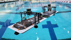
Constructed in 2016, the first roboat became the basis for the 1000 x 500 x 150 mm, quarter-scale, 3D-printable versions currently used in research by MIT and the AMS Institute (Figure 1). Each roboat has a single thruster in the middle of each edge, an inertial measurement unit (IMU) for recognizing inclination and velocity, a VLP16 LIDAR system from Velodyne Lidar (San Jose, CA, USA; www.velodynelidar.com), a forward-facing Intel (Santa Clara, CA, USA; www.intel.com) D435 RealSense camera, and an onboard computer with Intel i7 processor, 16 GB RAM, and 500 GB HDD.
The roboats are a far cry from the modular elements envisioned over two decades ago by early research into reconfigurable waterborne structures.
Shipping containers and humble beginnings
The concept of using mobile offshore bases (MOB) to support military operations, studied from 1997 to 2000 by the United States Office of Naval Research (Arlington, VA, USA; www.onr.navy.mil), proposed creating waterborne landing fields for aircraft using “one or more serially connected modules…with the capability to adjust size and/or length.”
The individual modules would be semisubmersible and had an estimated cost of $1.5B each. A method for disconnecting and reconfiguring modules via a multi-module dynamic positioning system was referred for further study. In 2001, the Institute for Defense Analyses (Alexandria, VA, USA; www.ida.org) determined that other solutions were more cost effective and the MOB project terminated.
In 2014, researchers from the GRASP Lab and Department of Mechanical Engineering and Applied Mechanics from the University of Pennsylvania (Philadelphia, Pennsylvania, USA; www.upenn.edu), in partnership with DARPA (Arlington, VA, USA; www.darpa.mil), tested the concept of a Tactically Expandable Maritime Platform. The research paper that reported the experimental results (bit.ly/VSD-SAB), Self-Assembly of a Swarm of Autonomous Boats into Floating Structures, described the creation of 1:12 scale, modified ISO shipping container modules (bit.ly/VSD-ISO) with one water wheel-type thruster positioned at each corner of the boat.
The system developed at the University of Pennsylvania used fiducial markers called AprilTags (bit.ly/VSD-APR) for monitoring the locations of the modules. Like QR codes, AprilTags only carry between 4 and 12 bits of data for easier, more robust tag reading from long distances. AprilTags also are designed for high localization accuracy to enable the calculation of the precise 3D position of the marker with respect to a camera, making AprilTags useful in the field of robotics.
Each module bore a paper AprilTag read by one or more cameras mounted to a frame 3.7 m above the pool. The cameras attached via USB cable to a laptop ran an AprilTag recognition package named cv2cg (bit.ly/VSD-CV2) and monitored module locations at a rate between 20 and 30 Hz.
A central computer fed module position information to coordinator software that parsed blueprints for desired shapes. The blueprints fed to an assembly planner that controlled the docking order for the modules. A trajectory planner then set the required travel paths and transmitted data to the modules.
In testing conducted in an indoor swimming pool, the modules configured into a landing pad for a manually-piloted quadcopter drone and a bridge between two sides of the swimming pool on which to drive a remote-controlled car.
Preparing to dock
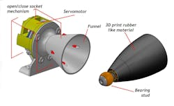
The system currently being developed by MIT features two major differences from the University of Pennsylvania system. The U. Penn system used a hook-and-wire mating technique requiring relatively precise maneuvering, whereas the MIT system uses a ball-and-funnel latching system (Figure 2) resembling the technology used in autonomous underwater vehicle (AUV) docking systems and allows more room for positioning error without a failed mating attempt. The second, more important difference regards the roboats’ vision systems.
“The University of Pennsylvania’s system relies on an overhead camera, meaning they use a centralized control strategy,” says Luis Mateos, a Robotic Researcher at the MIT Roboat project. “Each of our roboats is self-controlled.”
No movement commands are sent from a central control mechanism. The roboats act like a drone swarm, independent units that take collective action via communication with each other.
The Senseable City Lab researchers at MIT, currently focused on perfecting the ball-and-funnel latching system, use a pair of roboats for their research. One roboat performs station keeping maneuvers while the second roboat practices docking attempts, seeing one another via Intel RealSense cameras tracking paper AprilTags. The research takes place in a swimming pool on MIT campus and in the nearby Charles River.
Waking the roboat swarm
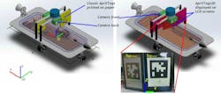
Another ten of the quarter-scale roboats are under construction to begin variable configuration tests. These versions will have two LCD screens mounted on each side of the vehicle for AprilTag marker display (Figure 3). The roboats will also have stored in memory a lexicon of AprilTags describing any and all maneuvers a roboat may require for navigating into mating position with another roboat, to help form a specific shape.
According to Mateos, every configuration begins with a captain roboat that organizes the construction effort in a domino-type fashion. The captain roboat orders the first set of docking maneuvers, the first set of docked roboats issue further orders to other roboats, and the cascading series of commands eventually leads to the formation of the completed shape.
“This captain roboat needs to be controlled/programmed by a human at some point,” says Mateos. For instance, a command might be broadcast for the swarm to take a specified shape at a specified location. This command may be transmitted via WiFi to any roboat in the swarm which then becomes the captain, publishing the information to the rest of the swarm to begin the chain of cascading docking maneuvers.
Glare—which creates camera noise—poses a potential problem when using LCD screens, which is why this system uses a pair on each side of the roboat. Placing these screens at different angles on each side of the roboat may provide a solution, since both screens won’t display glare from the same angle of incoming light.
“If one marker is obscured by glare or the camera otherwise cannot detect the tag, then we have another marker,” says Mateos. “By knowing the angle between the tags, we can know how much certainty we have in positioning the roboat.”
Next hurdles
Roboats forming pedestrian spaces must be flat. The quarter-scale roboats feature LiDAR scanners on a mounting bar running up and over the middle of the roboat. To solve this problem, Mateos says the researchers are imagining a system that functions like the roof on a convertible automobile.
“When LiDAR is required, the mounting bar activates, and it comes up. When LiDAR isn’t needed, the mounting bar goes down,” says Mateos. “Then a door closes over the compartment where the mounting bar is hidden, creating a flat surface on the roboat.”
Ideally, future iterations of the roboats will address the issue by not using LiDAR at all.
“Like autonomous cars, the roboats use LiDAR for localization and obstacle avoidance,” says Mateos. “What autonomous car designers are trying to do is only use cameras. The prices will go down, the systems will be less complex, but the artificial intelligence will be improved.”
The research team at MIT will at the end of 2019 begin construction of a full-scale roboat, which will have all the capabilities of the quarter-scale testbed roboats, with an expected completion date of 2021, according to Mateos.
Related stories:
Autonomous robot successfully completes highly-organized product packaging
3D laser scanner system targets underwater inspection applications
TuSimple announces $215M round of Series D funding
Share your vision-related news by contacting Dennis Scimeca, Associate Editor, Vision Systems Design
SUBSCRIBE TO OUR NEWSLETTERS
About the Author

Dennis Scimeca
Dennis Scimeca is a veteran technology journalist with expertise in interactive entertainment and virtual reality. At Vision Systems Design, Dennis covered machine vision and image processing with an eye toward leading-edge technologies and practical applications for making a better world. Currently, he is the senior editor for technology at IndustryWeek, a partner publication to Vision Systems Design.


