Telecentric lenses achieve precise measurements
By Andrew Wilson,Editor
Coupling telecentric lenses with a CCD camera and lighting helps systems integrators produce high-resolution images.
In many machine-vision applications, parts with complicated shapes must be imaged with high accuracy. This task is especially crucial when three-dimensional parts are inspected. In such applications, conventional lenses are apt to produce distorted images. To overcome this problem, systems integrators are coupling telecentric lenses with CCD cameras to capture images that yield constant magnification over a defined working-distance range.
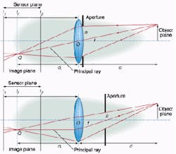
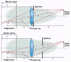
In conventional lens systems, each point on the object plane is projected onto a single point on the image plane. When the focus setting is moved, the image is blurred over a circular region in the sensor plane, with the object of interest being at the center of the circle. Because the principal ray's intersection varies with the position of the sensor plane, defocusing the system will vary the image magnification. "The same effect occurs if the object distance changes," says Spencer Luster, president and founder of Light Works (Toledo, OH). "In fact, it has been my experience in most practical cases that variation of the object distance is the usual culprit," he says.
FIGURE 1. In a conventional lens system, each point on the object plane is projected onto a single point on the image plane (top). When the focus setting is moved, the image is blurred over a circular region in the sensor plane, with the object of interest being at the center of the circle. Because the principal ray's intersection varies with the position of the sensor plane, defocusing the system will vary the image magnification (bottom). In a telecentric lens system, the chief rays for all points across the object or image are collimated. In a simple lens system, this result can be achieved by adding an external aperture to a conventional lens. The principal ray of the object being imaged will emerge parallel to the optical axis. As a result, the principal ray's intersection with the position of the sensor plane does not vary and defocusing the system will not cause any change in the magnification of the image.
In a telecentric lens system, the chief rays for all points across the object or image are collimated. In the simplest telecentric lens systems, this can be achieved by adding an external aperture to a conventional lens system (see Fig. 1). In such systems, the principal ray of the object being imaged will emerge parallel to the optical axis. As a result, the principal ray's intersection with the position of the sensor plane does not vary and defocusing the system will not cause any change in the magnification of the image.
Telecentric lenses
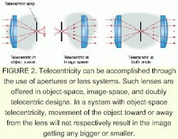
In practice, telecentricity can be accomplished through the use of apertures or lens systems. Such lenses are offered either as object-space, image-space, or doubly telecentric designs (see Fig. 2). "In a system with object-space telecentricity, movement of the object toward or away from the lens will not result in the image getting any bigger or smaller," says Jim Michalski, chief scientist at Edmund Industrial Optics (Barrington, NJ). "And, an object that has depth or extent along the optical axis will not appear as if it is tilted," he adds. For gauging applications, this is a useful property because a cylindrical object whose cylindrical axis is parallel to the optical axis will appear to be circular in the plane of a telecentric lens.
Although object-space telecentricity is difficult to illustrate on a printed page, researchers at the University of Edinburgh (Edinburgh, Scotland) have recorded a visual demonstration of telecentricity on the university's Web site (see p. 58 for details). On the site, a sequence of images is shown as the focus-setting f/12.5-mm lens from Nikon Instruments (Melville, NY) is varied. Optical flow vectors computed between frames show that the magnification varies significantly with the focus setting. After converting the lens to a telecentric one by adding an external aperture, another sequence of images shows the effects of varying the focus setting of the telecentric lens. In this sequence, optical flow vectors are negligible, demonstrating the magnification invariance of telecentric lenses.
While the effect of varying focus on magnification is shown dynamically on the university's Web site, the effects of distortion caused by parallax can be shown statically. When pin straightness in a semiconductor is examined using standard optics, the image may be correct at the center part, but objects will be distorted at the periphery. This information may not be usable, and the camera may have to be moved over the center of the image using an x-y stage. Such a procedure can slow the inspection process. By using a telecentric-lens system, system integrators can reduce the distortion caused by parallax and obtain a less distorted image (see Fig. 3).
Differentiating lenses
Whereas many machine-vision systems use object-space telecentric lenses, such lenses also can be built so that the principal rays arrive at the lens in parallel to the optical axis. In such image-space telecentric designs, image-plane movements to focus or defocus the system will not change the image size.
"In effect," says Shree Nayar of the department of computer science at Columbia University (New York, NY), "these lenses realize precise orthographic projection and are constant-magnification focusing." Because of these properties, such lenses tend to be used in profile projectors in the semiconductor industry where magnification changes caused by the variation of object distance from the camera lens are a serious problem.
FIGURE 3. When the straightness of pins in a semiconductor is examined using standard optics, the image may be correct at the center of the part, but objects will be distorted at the periphery (top). A telecentric-lens system can reduce the distortion caused by parallax and obtain a better image (bottom right). Photo Courtesy: Edmund Optics
Lenses built with a telecentric structure on both object and image side are often referred to as "doubly telecentric," "bilaterally telecentric," or, more correctly, "afocal" lenses. In doubly telecentric systems, the principal rays arrive and emanate from the lens in parallel to the optical axis. As such lenses are telecentric on both sides, a slight movement of the object or camera system will result in an increased accuracy over the use of an object-telecentric lens approach.
Billed as bilateral telecentric lenses, the Xenoplan series from Schneider Optics (Hauppauge, NY) is designed to operate with 2/3-in. CCD cameras and have adjustable iris and focus controls. Available with an image object magnification of 1 to 5, the lenses offer an image diameter of 11 mm and an object diameter of 11 to 55 mm. Telecentricity is specified as ranging from 0.018° to 0.046°, depending on which magnification is required.
Object oriented
Although object-telecentric lens systems provide constant magnification at variable working distances and are useful in imaging three-dimensional parts, the frontside of the optical system has to be at least as large as the object being imaged. Thus, telecentric lenses with large working areas can be both large and expensive. And, unlike the magnification of a standard lens that can be adjusted by changing the distance between the CCD sensor and the lens, telecentric lenses exhibit a fixed magnification.
FIGURE 4. Standard optical lenses and a diffuse back light are used to image plastic safety glasses. The resulting image shows a long vertical hair placed in the field of view for reference (top). The use of telecentric imaging and a diffuse back light shows a faint but sharp edged curving defect line called a viscous thread, which is left over from a previous molding (middle). With the use of collimated back lighting, this thread is prominently seen along with a large area (lower left) on which one surface is mildly deformed (bottom). Photo Courtesy: Light Works
In choosing a telecentric-lens system, developers should know the area of the object being inspected, the sensor size in the camera, and the distortion level that is acceptable. Most often, these parameters are specified in manufacturers' data sheets.
"Some telecentric-lens suppliers tell you about the telecentricity of their lenses by specifying the maximum angle that a chief ray makes with the optical axis," says Light Work's Luster. "Some do not even tell you this and simply state telecentricity as being less than 0.05°, without telling you what it means. That's no good for most people," he remarks.
"What is implied by a small angle for a telecentricity specification is a constant perspective and a small change in magnification for a large object distance change. But that is also not immediately useful. What the designer should examine is the magnification depth of field," Luster insists. In Light Work's Super-Eye line of lenses, for example, the magnification depth of field is specified at the limit of ±0.2%. Therefore, the magnification depth of field is the distance the object can move toward or away from the lens while still maintaining a magnification that is within 0.2% of the nominal.
Illumination considerations
Telecentric lenses provide an excellent means for accurate gauging applications but must be used in conjunction with proper illumination. When gauging thick objects with smooth and shiny surfaces using diffuse back lighting, for example, light rays coming from a far point on the diffuser may reflect off the object and make the object height appear smaller than it really is.
"One solution to this problem," says Luster, "would be to move the diffuser very far back, thus reducing the angles from which unwanted light could strike the object. Another solution would be to make the diffuser just slightly larger than the object. In the first case, you lose light and take up a lot of space. In the second case, you would lose object motion freedom," he adds.
Alternatively, a collimated light source can be used. Consider the use of standard optical lenses and a diffuse back light to examine plastic safety glasses. In this example, the resulting image shows a long vertical hair placed in the field of view for reference (see Fig. 4). Using telecentric imaging and a diffuse back light shows a faint but sharp edged curving defect line called a viscous thread, a thread of plastic left over from a previous molding. "Visually," says Luster, "this is extremely faint." With collimated back lighting, this thread can be prominently seen along with a mildly deformed surface area. In addition, a slight graininess over the whole field is revealed, due to a mild surface texture on the glasses.
In addition to keeping magnification constant while the focus changes, telecentric lenses also exhibit other important properties. In conventional lenses, brightness decreases as the effective focal length increases. In telecentric lens systems, however, image brightness remains constant. Consequently, telecentric lenses can take multiple images of a scene at different focus settings while the magnification is kept constant. This is accomplished by using a beamsplitter or a sequence of beamsplitters placed behind the telecentric lens to digitize multiple images simultaneously.
Company InformationDue to space limitations, this Product Focus does not include all of the manufacturers of the described product category. For information on other suppliers of telecentric lenses, see the 2001 Vision Systems Design Buyers Guide (Vision Systems Design, Feb. 2001, p. 74).Columbia University
Dept. of Computer Science
New York, NY 10027
Web: www.columbia.edu
Edmund Industrial Optics
Barrington, NJ 08007
Web: www.edmundoptics.com
Light Works
Toledo, OH 43624
Web: www.LW4U.com
Nikon Instruments
Melville, NY 11747-3064
Web: www.nikonusa.com
Schneider Optics
Hauppauge, NY 11788
Web: www.schneideroptics.com
University of Edinburgh
Edinburgh EH1 1HN, Scotland
Web: www.dai.ed.ac.uk/CVonline/ LOCAL_COPIES/CAVE/video-demos.html


