Smart Cranes Ease Load Positioning
Andy Wilson, Editor
At ports around the world, cranes are used to offload containers from ships. These cranes use a hook that is attached to a moving platform called a spreader that locks onto each container. To accurately position this spreader onto the container requires the crane operator to carefully position the spreader over the container.
"At sea," says Joseph Discenza, president of SmartCrane, "this task proves difficult since the yaw, pitch, and roll of a ship makes it complicated for the operator to discern the correct orientation of the crane hook." As a subsidiary of Daniel H. Wagner Associates, SmartCrane was founded to exploit the company's expertise in automated crane operating systems.
"Moving loads by crane is dangerous and time consuming," says Discenza, "and requires extensive operator training to minimize the amount of sway that is induced by the motion of the crane's trolley that is used to move the hook to the correct position." To minimize this sway while allowing the crane to be safely moved at its maximum rated speed, the company has developed a combined open- and closed-loop motion control system based on its proprietary Anti-Sway software that prevents dangerous sway and stops the load precisely at its target destination.
Residual sway
"Even when such systems are deployed," says Discenza, "residual sway due to 'nonvertical' lift and other effects can come into play. For example, if the suspension point of the hook is not positioned over the center of gravity of the crane hook, the load will sway. These effects can also be caused by wind or if the crane operator inadvertently hits another object while lifting the load."
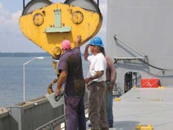
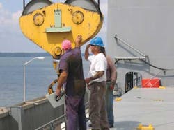
SmartCrane has developed a smart camera system that incorporates an inertial measurement unit (IMU) and a tilt encoder that provides correct positional accuracy of the crane hook. In this closed-loop motion control system, a smart machine-vision camera system is mounted on the crane's trolley above a passive reflector on the head block or hook (see Fig. 1). The system can use the camera tracking data to remove sway at initial hoist and to make final adjustments to minimize both residual sway and position error simultaneously.
"Onboard a ship," says Discenza, "it is not easy for an operator to determine the vertical position of the frame of the head block or hook since effects such as pitch, roll, and yaw provide a false sense of this orientation." Thus, the smart camera can also be used in systems -- that may or may not incorporate sway control -- to dynamically track the head block or hook while providing a vertical view of the head block.
Embedded vision
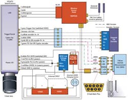
To achieve dynamic tracking, Discenza and his colleagues have designed an embedded vision system that combines a smart camera with a tilt encoder and IMU that is used to transmit positional information of the head block to a console in the operator's console (see Fig. 2). A VC4472 smart camera from Vision Components fitted with a 12-mm lens is used to capture and process 1600 × 1200-pixel × 8-bit images from the test target mounted on the hook.
"In this way," says Discenza, "targets up to 30 m from the system can be resolved by the camera." Because the smart camera features on-board I/O, it can also be used as a smart controller to measure both the inputs from a Falcon GX IMU from O-Navi and an external tilt controller. Both of these are powered by the VC4472 smart camera and transfer data to the camera over a serial interface.
"By integrating a 32-bit RISC CPU with three MEMS angular rate gyros and three MEMS accelerometers in one unit," says Discenza, "the IMU provides both the angular rate of change and the acceleration of the embedded system in x, y, and z directions. This information can be filtered to provide an accurate vertical position of the target in three-dimensional space."
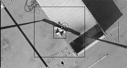
The data, along with images captured between 6 and 10 frames/sec, are transmitted over a WAP54G Wireless-G access point from Linksys to a host computer in the crane operator's cabin (see Fig. 3). Here, an image is displayed that shows the position of the target and the correct vertical orientation of the crane hook that is shown as a circular overlay.
Sophisticated software
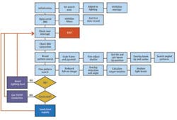
To program the system, Discenza used the Xcode integrated development environment (IDE) from Apple Computer. After the code was developed in C using the Xcode IDE, it was ported to run on the VC4472 Smart Camera's embedded TMS320C64 using Code Composer Studio from Texas Instruments. Because the code runs fully autonomously in the smart camera, no embedded PC was required. In operation, the code controls both the operation of the camera, data acquisition from the IMU, and tilt controller and transmission of the data to the host CPU (see Fig. 4).
The software is divided into a nine-stage loop that, after performing system initialization, opens the serial interface to the IMU, checks user interrupts, IMU corrections, and performs broad and fine pattern searches on the image. In the first initialization stage, a search area is set to determine in which part of the image the target is most likely to lie.
Since lighting conditions can vary depending on what time of day the system is used, for example, a histogram analysis is performed on this image and the shutter of the camera dynamically adjusted to obtain the best contrast. Overlays are then set to show the operator the correct vertical position of the hook or head block. This is accomplished in the next stage by filtering the serial data that are returned from the IMU.
Once an image has been properly exposed, a broad pattern search is performed on the previously determined search area. To speed this search, the image is first subsampled using pyramid processing that reduces the image size by a factor of 16. This smaller, subsampled image is then compared with a number of known target patterns that are rotated to varying degrees.
Once the target pattern has been located in the subsampled image, a smaller, high-resolution pattern can be located in pyramid space. Then, an edge-detection algorithm is used to determine the angle of the target and thus how it is rotated. These positional data are then used to show the operator how the crane hook or head block is positioned relative to the true vertical position of the crane.
Using such tools, the operator is provided with accurate positional data with which a load can be safely moved. The system was tested with other antisway technology developed by the United States Navy on a shipboard pedestal crane used to move containers or other cargo from ship to ship or ship to shore. At present these systems are developmental and have not been deployed by the Navy.
"However," says Discenza, "the smart-camera-based system was demonstrated in a system where the positional information from target data could be used in conjunction with antisway technology to further reduce the effects of residual sway due to nonvertical lift effects."
Company Info
Apple Computer
www.apple.com
Daniel H. Wagner Associates
www.wagner.com
Linksys
www.linksys.com
O-Navi
www.o-navi.com
SmartCrane
www.smartcrane.com
Texas Instruments
www.ti.com
Vision Components
www.vision-components.com
