Recent advances in technology, especially the emergence of "software-like" hardware-description languages (HDLs) and design tools, are facilitating the development of real-time imaging hardware and blurring the distinction between hardware and software development. For example, the emergence of high-capacity field-programmable gate arrays (FPGAs) affords the opportunity for developing real-time machine-vision "systems-on-chip" with significantly lower nonrecurring engineering costs than traditional application-specific integrated-circuit processes.
Technology advances in electronic design automation (EDA) are making dedicated imaging hardware development more accessible and less imposing. Hardware-description languages are one aspect of this trend. They provide a software-like syntax for describing the structure and behavior of electronic circuits. Their associated tools provide integrated development environments that permit the HDL design to be captured and simulated on common PC platforms. These tools also provide the capability to analyze circuit timing and to "synthesize" a design into a binary "bitstream" for programming the FPGA.
The EDA tool suites currently available offer the possibility of "virtual hardware development," whereby an electronic vision system can be designed and tested on a PC and ultimately instantiated in several different hardware incarnations. Just as programming-language standards and tools have enabled development of portable software, so do HDL standards and EDA tools enable the development of "portable hardware."
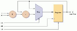
Multiplier-accumulator (MAC) logic circuit accepts input signals n and m, multipies them together, and accumulates the sum in the Register. This operation would be repeated four times to multiply each of the four SIZE samples (see listing 1) by the corresponding coefficients to obtain the resultant q-overflow value.
One major HDL is VHDL—very-high-speed integrated-circuit hardware-description language. Developed as a result of a US Department of Defense research program to improve the interchange of integrated-circuit design data, VHDL was adopted as IEEE Standard 1076-1987.1 The first revision was adopted as IEEE Standard 1076-1993. Another standard HDL known as Verilog, which was created in 1984 by Gateway Design Automation, has become a de facto standard for ASIC development.2 Verilog was adopted as IEEE Standard 1364-1995.
A multiplier-accumulator (MAC) circuit example, which is applicable to real-time image processing, is used to introduce some of the concepts underlying VHDL and how it compares with software-development languages. Many digital-signal and image-processing operations such as filtering can be reduced to a sum-of-products form. A MAC is used to implement the sum-of-products operation such that an array of data samples is multiplied by an array of coefficients and summed to produce a result.
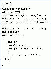
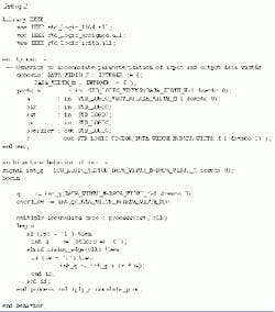
A fragment of C code illustrating a MAC function is shown in Listing 1. A block diagram of a MAC logic circuit and its associated VHDL are shown in the figure and Listing 2, respectively. The code multiplies an array of integer samples (d1[i]) by an array of integer coefficients (d2[i]) and accumulates the result in the integer variable, result.
This MAC circuit accepts two input signals, n and m, multiplies them together, and accumulates the sum in the register. In the figure, this operation would be repeated four times to multiply each of the four (Size) samples by the corresponding coefficients, producing the resultant value that is available via signal q. For simplicity, the circuitry required to cycle through the samples and coefficients (the equivalent of the for loop in the C code) is not shown. Note, however, that one approach for the logic-based MAC would be to implement four MACs, resulting in a parallel-processing implementation with a significant performance advantage over the CPU-based approach.
Three forms
VHDL can be expressed in three different forms: behavioral, structural, and dataflow. The behavioral form defines the behavior of a logic circuit, normally using a process, which consists of a set of sequential statements indicating how the logic behaves. This form most closely parallels that of software programming, but does not necessarily lead to the most efficient logic circuit implementations.
Libraries are used in VHDL to store component designs; declaring them with the library statement makes the designs available for use by a VHDL program (see listing on p. 28). The use statement declares specific packages (collections of declarations that define the interface to the components) to be used in the program. The use statement exposes the interface to selected components while the implementation details remain hidden in the library. Libraries and packages in VHDL are used to implement the concepts of encapsulation and data hiding found in third-generation software languages such as C, C++, and Ada.
VHDL has a notion of "black boxes" in which a component can be defined by its interfaces; the implementation details are hidden within the black box and are not of concern to the user of the component. A VHDL black box is called an entity. The entity declaration in Listing 2 defines the interfaces to the mac component—a multiplier-accumulator. The black-box paradigm promotes the software engineering concepts of abstraction and component reuse. The hierarchical nature of black boxes in VHDL strengthens the power of abstraction.
The generic statements within the entity declaration define constant values to be used in the program, much as a #define statement could be used in C. In the mac program, these generics are used to parameterize the implementation for different sizes of data and coefficients. This powerful ability to create parameterized components is a major advantage of VHDL over schematic-based designs.
The port declaration for the entity defines the signal interfaces (inputs and outputs) to the component. The signals n and m represent the data and coefficient inputs to the mac; each input is 8 bits wide as specified by the generic parameters. The clk signal is a clock input that controls the timing and operation of the mac. The rst signal is a reset signal used to set the register contents to zero. The ce signal is a clock enable that can be used to disable or turn off the operation of the mac. The signal q is the mac output and is 16 bits wide to accommodate the full precision of the multiplication. The signal overflow is a one-bit output signal to indicate an overflow condition. Note the concept of strong-typing, analogous to that used in C++ or Ada, in which both the direction (in or out) and data type (STD_LOGIC) of the signals are declared.
An architecture in VHDL is the construct containing the implementation of an entity, analogous to the code for a function in C or a method in C++. In the mac example, the architecture is named behavior, indicating that it contains a behavioral implementation of mac. The signal declaration for int_q immediately following the architecture statement is an internal signal that is defined to allow the current register value to be used in the mac operation. Because q is defined as an output value, it cannot be read by internal circuitry. Note the begin and end statements that clearly define the scope of the architecture implementation.
The multiply_accumulate_proc process contains the sequential code that defines the behavior of the mac. The if-then-elseif statements are used to define conditional behavior much as they would in C or C++. The process includes a sensitivity list that defines signals that cause the process to be executed. In this way, VHDL features event-driven behavior. In the example, the process is sensitive to the signals rst and clk - a level change in rst (from 0 to 1 or vice versa) or a clock transition (rising edge of clk) causes the statements in the process to be executed. The heart of the implementation is the multiply-accumulate function (int_q <= int_q + (n * m)), which occurs on the rising edge of the clock clk, provided the circuit is enabled (the level of ce is a logical 1).
Software developers desiring to keep their skills in embedded and real-time systems development up to date should become more familiar with hardware development using HDLs.—Ronald B. Hawkins
REFERENCES
- S. Rajan, Essential VHDL-RTL Synthesis Done Right, S&G Publishing (1998).
- M. D Ciletti, Modeling, Synthesis and Rapid Prototyping with the Verilog HDL, Prentice Hall (1999).
ACKNOWLEDGMENT
The author wishes to thank Ken Welch and Allen Tung, digital hardware engineers at VisiCom, for preparing the example used in this article.
RONALD B. HAWKINS is chief operating officer of the computer products division, VisiCom, San Diego, CA.


